Manual Shrinkage Compensation
Material shrinkage occurs in thermosets as they transition from liquid state to solid state during the curing process.
3D Sprint has features that allow the user to compensate for the natural shrinkage of the material in order to fine tune the accuracy of a part.
Usually these values are set automatically for printer and material combination, however additional measurement and calibration may be required with certain geometries. The number of iterations required to achieve desired accuracy can vary based on geometry, post processing and general machine settings. This process can be performed in any build modes to fully understand how parts may behave in that particular mode.
The following instructions will explain the process for entering shrink compensation and calibrating a machines using standard calibration parts.
Manually Setting Scaling Values
Open the Printer command from the Print tab.
Select the Printer, Material, Printer Mode and Build Style as required.
In the Style Set step, select one of the standard style presets in the list of style presets.
Click Copy
 to create a new Build Style
based on the existing style set, and then enter a name.
to create a new Build Style
based on the existing style set, and then enter a name.
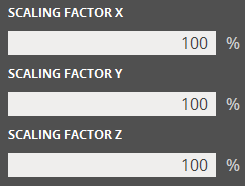
Modify the Scaling Factor (X,Y,Z) to include the Shrinkage Compensation values.
(Optional) Add a description for the Build Style.
Click Apply to save and apply the build style.
Calculating Shrinkage Compensation Factors.
Build a Calibration Part (1st Iteration)
Use either a standard calibration part or create one using Generate Geometry (a cube with 1,2,0.5 works).
Set up build with the part facing the correct axis on the platform.
Build and post process calibration parts using standard cleaning methods.
Take Measurements and Determine Scaling Factor
Calculating the Scaling Factor
Use the following formulas to determine the required scaling factor:
X Scaling Factor = (XCAD - XPART)/ XCAD * 100% (answer will be as a percentage)
Y Scaling Factor = (YCAD - YPART)/ YCAD * 100% (answer will be as a percentage)
EXAMPLE:
X measurement of CAD model = 3.000”
Y measurement of CAD model = 5.000”
X measurement of printed part = 2.998”
Y measurement of printed part = 4.989”
X Scaling Factor = (3.000 – 2.998)/3.000 *100 = 0.067%
Y Scaling Factor = (5.000 – 4.989)/5.000 * 100 = 0.22%
Enter Scaling Factor for a Repeat Build (2nd Iteration)
Open 3D Sprint and select the desired printer.
Load the calibration part(s).
Follow the instructions at the top of this page for Manually Setting Scaling Values.
Make individual x, y and z adjustments.
In the previous example, the x scaling factor should be 100% + 0.067% = 100.067%
The y scaling factor should be 100% + 0.22% = 100.22%\
Enter these two numbers in the corresponding Scaling Factor boxes for X and Y.Build and post process calibration parts using standard cleaning methods.
Note: Additional measurement and calibration may be required with certain geometries.