Supported Printers:
SLS-printers
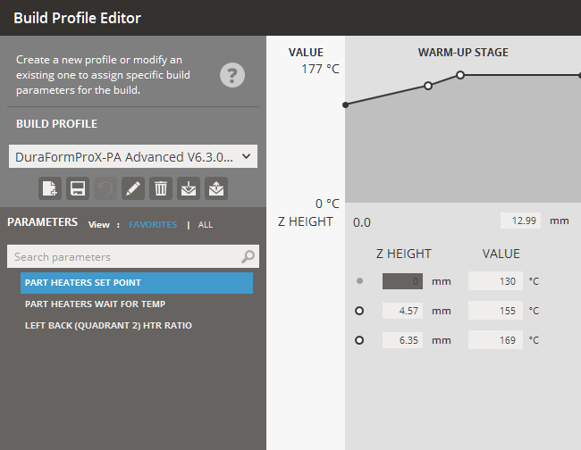
By default, the Build Profile assigned is defined during the configuration of printer and materials when setting up printer in the Printer command. However the Build Profile Editor allows you to create a new profile or modify an existing one to assign specific build parameters to a job, it will define the behavior of the build at various Z levels during the print. Build Profiles are assigned to an entire print build. Please see How Parameters Work for a more general overview of parameters.
Loading and Saving Profiles
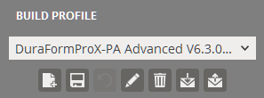
Build Profiles can be saved and loaded in the Build Profile Editor.
To load a saved set of parameters:
To export a saved set of parameters:
To create a new set of parameters:
To update a set of parameters:
If necessary, click Rename ![]() to rename the selected build profile
and then change to a new name in the Name
box.
to rename the selected build profile
and then change to a new name in the Name
box.
To delete a set of parameters:
To restore parameters to the default values:
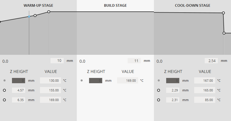
Build Stage
|
Build Profiles are broken up into three stages, Warm-Up stage, Build stage and the Cool-Down stage. The Z height of each stage can be set in the Build Profile Editor interface.
For each parameter, you can tell the system what values to use at various Z levels during the stage of the build; this is called a profile. You can click to create a point on each stage to create a row in the table for the each Z height when the parameter should change. The values of points can be changed by either modifying the values below the graph or by clicking and dragging the points on the graph. To delete a point, select it by clicking it on the graph and press delete from the popup dialogue. If you intend for a parameter to use the same value throughout a build, its table should have only one row, with a Z height of 0.000 and the desired value. |
Build Profile Parameters
The complete set of parameter can be viewed by selecting ALL under parameters.
Please see How Parameters Work for a more general overview of parameters. Also, some parameter can contain a location within the unit <Right/Left/Top/Middle/Bottom/Front/Back>
(Part) Cylinder Heater Enable - Turns on the part cylinder heater. A zero (0) turns it off; 1 turns it on. (Part) Cylinder Heater Output Limit- The percentage of duty cycle that determines the power available from the part cylinder heater. (Part) Cylinder Heater Set Point- The temperature at which the part cylinder heater is controlled. Cooldown Wait for Temp Duration - Entering a value for this parameter requires that the build wait for the temperature to be at or near the setpoint temperature before beginning to the cooldown stage. Waiting for temperature prevents the cooldown stage from starting before conditions are optimum. (Stepped) Fast Add Powder Layer - When on (1), this feature causes the system to begin scanning parts as soon as the roller passes the part piston. When off (0), the system waits until the roller completes its trip across the part bed to begin scanning. Feed Powder Amount- The amount of powder dispensed on top of the Sweeper that the Sweeper deposits on the bottom left feed heater. The amount is measured in feed roller revolutions; more revolutions = more powder dispensed. NOTE: When this feature is enabled, your parts will build faster, but you will have little or no time to notice and respond to a short feed. Front / Back Corner PB-HTR Duty Cycle - The percentage of duty cycle that determines the power available from the Front / Back Corner PB-HTR (or limits the percentage of time the heater is on). HFM Left Heater Output Limit - The percentage of duty cycle that determines the power available from the left feed heater (or limits the percentage of time the heater is on). HFM Left Heater Set Point - The temperature at which the left feed heater is controlled. HFM Right Heater Output Limit - The percentage of duty cycle that determines the power available from the right feed heater (or limits the percentage of time the heater is on). HFM Right Heater Set Point - The temperature at which the right feed heater is controlled. L --> R Roller Rotation Ratio - Literally, the ratio of [the rotation speed of the counter-rotating Roller's drive motor] to [the rotation speed of the Sweeper's transverse drive belt motor]. Effectively, this parameter determines how fast the Roller counter-rotates as the Sweeper travels from side to side. The greater the ratio, the more revolutions the Roller makes per unit of Sweeper travel. L --> R Roller Traverse Speed - The velocity at which the Sweeper traverses the part bed in inches per second. Changing this parameter causes the Roller to counter-rotate faster or slower in order to keep the Roller Rotation Ratio constant. R --> L Roller Rotation Ratio - Literally, the ratio of [the rotation speed of the counter-rotating Roller's drive motor] to [the rotation speed of the Sweeper's transverse drive belt motor]. Effectively, this parameter determines how fast the Roller counter-rotates as the Sweeper travels from side to side. The greater the ratio, the more revolutions the Roller makes per unit of Sweeper travel. R --> L Roller Traverse Speed - The velocity at which the Sweeper traverses the part bed in inches per second. Changing this parameter causes the Roller to counter-rotate faster or slower in order to keep the Roller Rotation Ratio constant. Laser Window Heater Set Point - The temperature at which the laser window heater is controlled. Left / Right Feed Distance - The distance the feed piston (that is closest to the roller at the beginning of the Add Powder sequence) moves up prior to roller motion and leaves the powder level above the surface. The feed distance represents the height of new powder to be placed on the part bed. Left / Right Feed Heater Output Limit - The percentage of duty cycle that determines the power available from the feed heater (limits the percentage of time the heater is on). Left / Right Feed Heater Set Point - The temperature at which the feed heater is controlled. If the powder is too hot, the roller may not be able to deliver the material. If the powder is too cold, the part may curl Left / Right Feed Heater Wait for Temp - Entering 1 for this parameter requires that the build wait for the temperature to be at or near the setpoint temperature before adding a layer. A zero means this restriction does not apply. Waiting for temperature helps ensure that the feed powder is at the correct temperature before the system adds a layer of powder. (Stepped) NOTE: If you begin a build with powder that is already warm and you have ramped values for the feed heaters, it is possible that the SLS system may not reach the setpoint and may alarm out of the build. This is due to the fact that the feed heaters will reach their first setpoint and (while waiting for the part heater to reach its setpoint) then go beyond the next ramped setpoint. This is caused by radiant heat from the part bed. You can avoid this situation by setting Wait for Temp to zero during the warm-up stage if the powder is already warm. Left / Right Feed Powder Amount - The amount of powder dispensed on top of the Sweeper that the Sweeper deposits on the bottom left/right feed heater. The amount is measured in feed roller revolutions; more revolutions = more powder dispensed. (Stepped) Right Back (Quadrant 1) HTR Ratio - The duty cycle ratio for the quadrant 1 heater. Left Back (Quadrant 2) HTR Ratio - The duty cycle ratio for the quadrant 2 heater. Left Front (Quadrant 3) HTR Ratio - The duty cycle ratio for the quadrant 3 heater. Right Front (Quadrant 4) HTR Ratio - The duty cycle ratio for the quadrant 4 heater. Left Inner HTR Ratio - The duty cycle ratio for the left inner heater. Right Inner HTR Ratio - The duty cycle ratio for the right inner heater. Minimum Layer Time - Specifies the minimum number of seconds between each add powder layer sequence in a build. This parameter allows you to have consistent layer time, regardless of the geometry that is being scanned. Part Heater Duty Cycle Offset - The percentage of right part heater's duty cycle that determines the power available from the [front, back, or left] part heater (or limits the percentage of time the [front, back, or left] part heater is on). Part Heater Inner/Outer Ratio - The duty cycle of the inner zone of the part heater is not controlled through a PID controller. Instead, the inner zone duty cycle is determined as a function of the duty cycle of the outer zone, which is controlled through PLC with feed back from the IR sensor. The inner zone duty cycle is equal to the outer zone duty cycle multiplied by the inner zone ratio. For example, if the duty cycle of the outer zone (or Zone 1) is 80 percent and the outer zone Ratio is 0.5, the duty cycle of the inner heater is 40 percent. Part Heater PID Output Limit - The maximum percentage of duty cycle that determines the power available from the heater (or limits the percentage of time the heater is on). This is the outer zone of the part heater. Part Heater Output Limit - The percentage of duty cycle that determines the power available from the right part heater (or limits the percentage of time the heater is on) Part Heater Set Point - The temperature at which the powder in the part cylinder is controlled. If the temperature is too high, the part bed could cake or the part bed could experience part growth; if the temperature is too low, the part could curl. Part Heater Wait For Temp - Entering 1 for this parameter requires that the build wait for the temperature to be at or near the setpoint temperature before beginning to sinter. A zero means this restriction does not apply. Waiting for temperature prevents sintering from occurring when conditions are not optimum. This parameter is only active during the build stage. Piston Heater Enable - When set to 1, enables the piston heater in the RCM. Piston Heater Output Limit - The percentage of duty cycle that determines the power available from the piston heater (or limits the percentage of time the heater is on). Piston Heater Set Point - The temperature at which the piston heater is controlled. Pre Add Powder Layer Delay <After Scan> - The number of seconds you want the system to wait before the roller moves to add the next layer of powder. Use this parameter to allow extra time for the current layer to cool or heat. Excessive delay increases processing time. Post Add Powder Layer Delay <Before Scan> - The number of seconds you want the system to wait after adding a layer of powder and before beginning to scan the next cross-section. This allows the powder to heat extra time before beginning the next scan. Excessive delay increases process time Powder Layer Thickness - The depth that the part piston lowers for each layer, which determines powder thickness of each layer in the part cylinder. If the layer thickness is too small, processing time increases. If too thick, the powder may not be properly sintered; it also may cause curling and jagged edges on inclined surfaces. Powder Layer Thickness is typically 0.004 to 0.006 inches (0.10 to 0.15 millimeters). Re-Feed Delay - The delay after Powder Return piston moves up, before traverse roller starts back to right. Roller Rotation Ratio - Literally, the ratio of [the rotation speed of the counter-rotating Roller's drive motor] to [the rotation speed of the Sweeper's transverse drive belt motor]. Effectively, this parameter determines how fast the Roller counter-rotates as the Sweeper travels from side to side. The greater the ratio, the more revolutions the Roller makes per unit of Sweeper travel. Roller/Sweeper Speed - The velocity at which the Sweeper traverses the part bed in inches per second. Changing this parameter causes the Roller to counter-rotate faster or slower in order to keep the Roller Rotation Ratio constant. Rotate Scan Order - When enabled, this parameter prevents parts from being scanned in the same order every layer. It increments the scan order before scanning the next layer. For example, if you scan parts, A, B, C, and D, on three consecutive layers with Rotate Scan Order enabled, the scan order for each layer would be: ABCD, BCDA, and CDAB. Smart Feed Enable - This parameter determines whether the system uses the Smart Feed feature (instead of the Left and Right Feed Distance parameters) to calculate the amount of powder to feed for each layer, based on the specific geometry of the layer Smart Feed Gain - This parameter is used to modify the built-in calculation of the Smart Feed feature. The calculated feed distances are multiplied by the value of the Smart Feed Gain parameter. The parameter defaults to a value of 1, for no change in the calculation. You can set its value between 0.7 and 1.3. Wait for Temp Duration - Entering a value for this parameter requires that the build wait for the temperature to be at or near the setpoint temperature before beginning to the cooldown stage. Waiting for temperature prevents the cooldown stage from starting before conditions are optimum. |
See Also