Supported Printers:
SLA-printers
Region styles are specific to a region and can be assigned to each region individually.
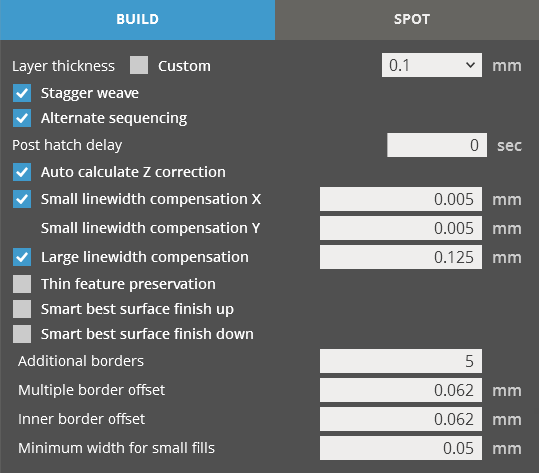
Build Parameters
|
Layer thickness - The thickness of each layer. Select Custom to redefine the layer thickness. Stagger weave - The positions of the hatch vectors change from layer to layer so that the hatch vectors of two consecutive layers are interlaced. This is applied to X and Y hatches only. Alternate sequencing - This option reduces curl distortion of the part. The sequence of drawing the hatch vectors changes from layer to layer. With two hatch (X and Y) and four propagation (Right to Left, Left to Right, Front to Back, and Back to Front) directions, there are eight drawing sequences through which it cycles. Post hatch delay - A delay time that is added to any layer with at least one hatch or fill vector that is greater than or equal to one inch long. The delay is added after all the hatch and fill regions are completed and before any additional borders are drawn. If supports occur on the layer, then the supports are drawn during the delay time in order to optimize throughput. Any remaining delay time will be counted down after the supports are finished drawing. Auto calculate Z correction - Automatically calculates the number of Layers of Z-Correction to be applied to the part, using Dp, Ec, layer thickness, hatch over cures, and fill cure depths. Small linewidth compensation X / Y - Used to compensate for the small width of the border vectors in X and Y directions, which delineate the perimeter of a layer. This parameter helps to preserve the overall dimensional accuracy of a stereolithography part. Note: Small linewidth compensation can be set as a default for all parts as a default build style in Printer Settings. Large linewidth compensation - Used to compensate for the large width of the border vectors, which delineate the perimeter of a layer. This parameter helps to preserve the overall dimensional accuracy of a stereolithography part. Thin feature preservation - Used to retain thin features against greater Z Compensation. Smart best surface finish Up / Down - Scan the part in a continuous X or Y propagation, jumping back and forth over holes or posts rather than scanning around one side of them and then returning to scan around the second side, thereby minimizing flaws in the up- and down-facing surface. Specify shell thickness - Used to specify the thickness of the shell surrounding the part. Note: The Specify shell thickness option is available for materials that support QuickCast Diamond build style. Additional borders - Number of additional borders. Multiple border offset - The offset value for multiple borders. Inner border offset - The offset value for inner border. Minimum width for small fills - The minimum width to create small fills. Number of fill layers - Used to specify the number of fill layers. Note: The Number of fill layers option is available for materials that support QuickCast Diamond build style. |
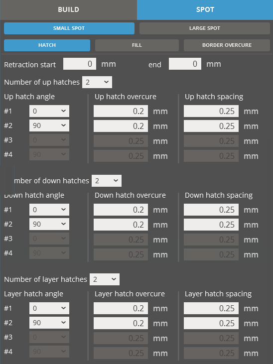
Spot - Hatch Parameters
|
Reaction start / end - The retraction start and end parameters specify the distance of the start and end points of the hatch vector from the border vectors. Retraction is sometimes useful for minimizing distortion, although part strength can be sacrificed with larger values. When a hatch vector is drawn, it can:
Number of (up/down/layer) hatches - The number of hatches defines how many passes of hatch exposure the laser beam applies to the parts. Hatch angle - The hatch angle describes the direction in which the laser beam travels back in forth as it scans. If the number of hatches is greater than one, then different hatch angles can be used for each pass of hatch. Hatch overcure - Defines the depth beyond the layer thickness to which the hatches are cured for a given pass of hatch. Different hatch overcure values can be used for each pass of hatch. Hatch spacing - The Hatch Spacing is the distance between adjacent hatch vectors. For EXACT and ThinLayer build styles, the distance is typically equal to about one-half of the beam width. For FAST build styles, the distance is typically about one beam width. QuickCast build styles usually use hatch spacings of greater than 0.050" (1.27 mm) in order to minimize the amount of material on the interior of the part. |
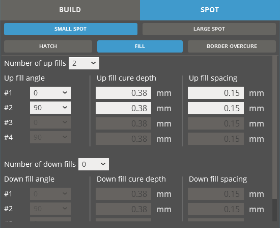
Spot - Fill Parameters
|
Number of (up/down) fills - Defines how many passes of fill the laser beam applies to the parts. Fill angle - Describes the direction in which the laser beam travels back in forth as it scans fills. If the number of fills is greater than one, then different fill angles are typically used for each pass Fill cure depth - Determines the absolute depth of curing for the fill vectors on a given pass of fill. Different fill cure depths can be specified for each pass. Fill spacing - Determines the spacing between adjacent fill vectors. |
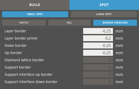
Spot - Boarder Overcure Parameters
|
Layer border - Defines the depth beyond the layer thickness to which the layer borders are cured for a given pass. Layer border prime - Defines the depth beyond the layer thickness to which the layer border primes are cured for a given pass. Down border - Defines the depth beyond the layer thickness to which the down borders are cured for a given pass. Up border - Defines the depth beyond the layer thickness to which the up borders are cured for a given pass. Diamond lattice border - Defines the depth beyond the layer thickness to which the diamond lattice borders are cured for a given pass. Note: The Diamond lattice border option is available for ProX 800 printers and materials that support QuickCast Diamond build style.
Support border - Defines the depth beyond the layer thickness to which the support borders are cured for a given pass. Support interface up border - Defines the depth beyond the layer thickness to which the support interface up borders are cured for a given pass. Support interface down border - Defines the depth beyond the layer thickness to which the support interface down borders are cured for a given pass. |
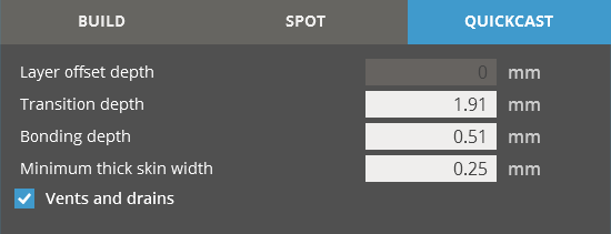
QuickCast Parameters
Note: The QuickCast parameters are available for the printers and materials that support QuickCast build style.
|
Layer offset depth - Allows you to change the height to which the square column is built before it is shifted along the X and Y axis. The position shift occurs throughout pattern building from bottom to top. The new position places the vertex of the subsequent column in the centroid of the previous column. Transition depth - The height to which two parallel sides of the hexagon are built before transitioning to build the next two parallel sides in a different direction. Bonding depth - The height in which the previous two sides of the hexagon continue to be built following the transition to the next two sides. This overlap helps the vectors in the new direction adhere to the previous vectors. Minimum thick skin width - A method of eliminating unnecessary Thick Skins to allow for easier drainage of narrow channels, which are built at an angle. Any feature that has a width that is less than twice this value, will not be given Thick Skins. Thick Skins are the result of filling up and downfacing regions for three layers. Vents and drains - Adds vents and drains to the pattern if a V_D file exists for the STL file. Vents and drains are used to remove trapped liquid resin from the completed pattern. Vents are created on up-facing surfaces, and drains are created on down-facing surfaces. |