Supported Printers:
SLS-printers
SLS Manufacturing is excellent for manufacturing lots of small, complex plastic parts, such as electrical connectors and clips. The cage command allows the placing of a structure around small parts to prevent them getting lost during break out and post processing. There are two operations available within this command:
Box - The box option generates a box shaped structure around selected part(s).
Freeform -The freeform option generates a cage structure based on the layout of selected part(s).
In the Print tab, click Cage.
Select one of the following action: Box or Freeform.
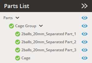
Cage Part List
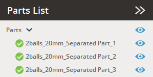
When creating a cage, the parts selected will be shown in the Parts List under a Cage Group. Each cage will create it's own grouping, and individual parts and groupings can be toggled as normal in the pars list.
 |
 |
Parts list before applying a Cage |
Parts list after applying a Cage |
Box
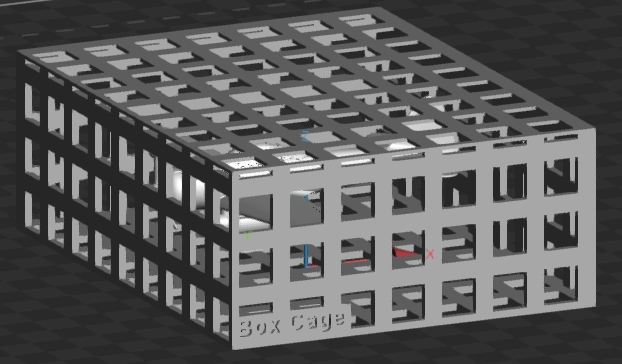
Box will create a cube shaped cage to encapsulate all of the selected parts in the Print Platform.
|
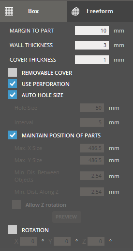
Box Parameters Margin to Part - Empty space in between a part and cage. Wall Thickness - The wall thickness of a cage. Cover Thickness - Cage top-cover thickness. The cover thickness is usually set thinner than the wall thickness so that it easier to break and remove parts after printing. Removable Cover - Determines whether to generate a removable cover of a cage. Use Perforation - Determines whether to generate holes or not on the surface of a cage. Auto Hole Size - Determines whether to automatically generate holes or to generate them using set values. Automatically generated holes take into account the part size so as not to allow small parts to fall out of the cage. Hole Size - The size of holes generated for perforations. Interval - The interval between holes generated for perforations. Maintain Position of Parts - Determines whether to maintain the positions of parts. If it is checked, the cage will be generated without changing the position of the parts and the generated cage may fall outside the printing area. If it is not selected, parts will be autoplaced and then the cage structure will be generated within the printing area. The maximum size of a cage in X and Y, the minimum distance between target objects, and the minimum distance along Z-axis can be defined manually. Allow Z-rotation - Allows parts to be rotated in Z-axis. Preview - Allows to preview parts to be rotated in Z-axis. Rotation - Cage rotation for space optimization along the X-, Y- or Z-axis. |
Select parts to include.
Modify the cage parameters as desired.
Click Next.
(Optional) Enter label details to be engraved on the generated cage structure.
|
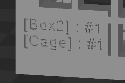
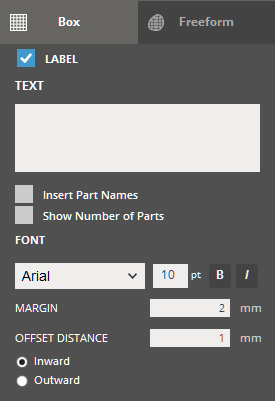
Text - Allows to insert texts to the box cage. Insert Part Names - Select to insert part names. Show Number of Parts - Select to insert text with the number of parts. Font - Allows to change the
font style and the size of text. Click Bold
Margin - Specifies the left and bottom margins of text. Offset Distance - Specifies the offset distance of text from the surface of the cage. Select offset distance and Inward or Outward direction.
|
Click Apply to create the cage structure or click Back to modify the parameters.
Freeform
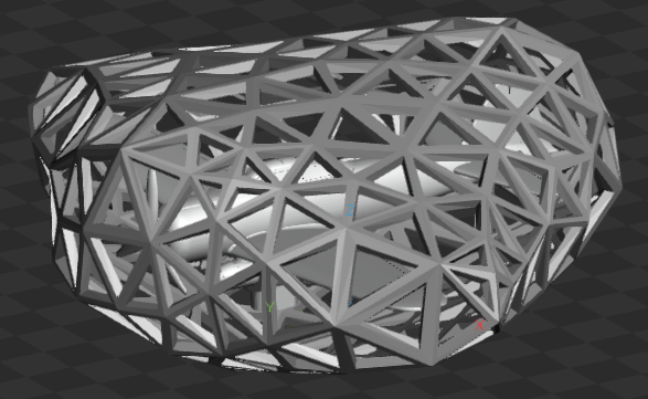
Freeform will generate a cage structure to encapsulate the parts based on the selected parts, and their position if Maintain Position of Parts is not selected, parts will be autoplaced before generating the cage.
|
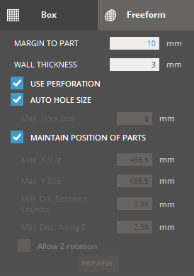
Freeform Parameters
Margin to Part - Empty space in between a part and cage. Wall Thickness - The wall thickness of a cage. Use Perforation - Determines whether to generate holes or not on the surface of a cage. Auto Hole Size - Determines whether to automatically generate holes or to generate them using set values. Max. Hole Size - Enter the maximum size of holes generated for perforations Maintain Position of Parts - Determines whether to maintain the positions of parts. If checked the cage will be generated without changing the position of the parts and the generated cage may fall outside the printing area. If it is not selected, parts will be autoplaced and then the cage structure will be generated within the printing area. The maximum size of a cage in X and Y, the minimum distance between target objects, and the minimum distance along Z-axis can be defined manually. Allow Z-rotation - Allows parts to be rotated in Z-axis. Preview - Allows to preview parts to be rotated in Z-axis. |
Select parts to include.
Modify the cage parameters as desired.
Click Generate.
Cage Presets
Save parameter changes as defaults for later use and restore them at any time you need.
![]()
![]() Set Defaults
- Click to set parameter changes as defaults for later use.
Set Defaults
- Click to set parameter changes as defaults for later use.
![]() Restore
Defaults - Click to restore any changes to the saved defaults.
Restore
Defaults - Click to restore any changes to the saved defaults.
![]() Restore
Factory Defaults - Restores any changes to the factory defaults.
Restore
Factory Defaults - Restores any changes to the factory defaults.
![]() Import Saved
Parameters - Click to import saved parameters.
Import Saved
Parameters - Click to import saved parameters.
![]() Export Parameters
- Click to export changed parameters for later use.
Export Parameters
- Click to export changed parameters for later use.