Make vent or drain holes in the part, to drain material after printing. This command requires a hollow part.
Note: Click Simple UI ![]() to switch between
the simple and the advanced User Interface. In the Simple UI, only the
tools for minimum workflow are visible.
to switch between
the simple and the advanced User Interface. In the Simple UI, only the
tools for minimum workflow are visible.
Note: The Vent Drain command is only available for parts using QuickCast materials and build styles.
In the Print tab, click Holes.
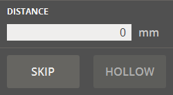
If the current model is not hollow, first select the part and choose thickness of resulting shell. Click Hollow.
Or, if the part is already hollow. Click Skip.
Note: If holes are placed on a non-hollow part, unexpected behavior may occur.
Select one of the following hole types and then type values
to specify the size and the orientation of the hole: Rectangular
Hole ![]() (Length / Width / Rotation), Round Hole
(Length / Width / Rotation), Round Hole ![]() (Diameter).
(Diameter).
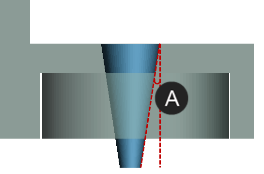
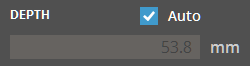
While the Auto is toggled on in the Depth option, the depth is automatically calculated depending on where you click on a part. To manually specify the depth of a hole, clear the Auto and type a value in the Depth option.
If necessary, in the Draft Angle option, define a daft angle for conical holes.
|
|
Position the mouse pointer over a part to see a preview of the size.
While the Snapping/Selection is toggled on, it allows the snapping of the pointer to part faces, or the selection of already created holes.

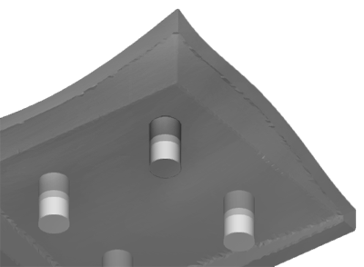
To place a hole, click on the part. The holes will be previewed on the part.
To remove a hole, select a hole and press Delete. To move a hole, select a hole and drag it to a new position on the part.
To place another hole, click on the part again.
To retain defined hole plugs and print them separately from the part, click Retain Hole Plugs. The Auto Place enables you to quickly place created hole plugs onto the Print Platform.

Note: The Auto Place option is available when the Retain Hole Plugs is selected.
Set the Clearance. This will create a clearance between the holes and the part, for example to make room for glue or printing error.
Note: The Clearance option is available when the Retain Hole Plugs is selected.
Note: The clearance will cut into the holes reducing its size.
Make sure that all holes are placed. Click Set to accept the hole creation.
Note: If the Retain Hole Plugs option is selected, the created hole plugs will be added as individual parts to the Parts List.
Note: The Vent Drain command will only be usable on parts using a QuickCast material and build style. Vents can only be placed on faces that are parallel to the Print Platform.
In the Print tab, click Vent Drain.
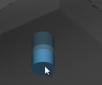
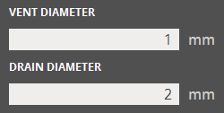
Enter a vent / drain size in the parameters. Position the mouse pointer over a part to see a preview of the size.
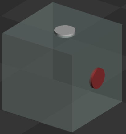
To place a vent or drain, click on the part. Vents in valid locations will show in blue, invalid locations will be in red.
After placing a preview will show position of the vent or drain in white.
To place another vent or drain, click on the part again.
Note: The Snapping/Selection option allows the snapping of the pointer to existing vent / drain holes. Click Snapping/Selection to easily select and move existing vent / drain holes.

When all vents and drains are placed, click Set.
Vents and drains will be visible on the part as a light colored circle once set.