Supported Printers:
ProJet MJP 2500 (all except IC)
ProJet MJP 5500X-E
ProJet MJP 5600
Note: Information on the process of creating an infill on the ProJet MJP 2500 IC printer can be found here.
This page contains information on how to change solid build material in the interior of a part into a combination of build material and air, a technique that may be used to reduce part weight and material use in printed parts. The resultant parts have a solid outer "skin" and a porous, sponge-like interior. Care must be taken to avoid over-weakening your parts and compromising the strength of gated locations. Extra care should also be taken when manually removing support wax from thin non-solid parts to avoid accidentally breaking them. Shrinkage factors (applied in 3D Sprint) may also need to be different than with solid parts.
No special software or add-ins are required, this feature is a standard toolset group in 3D Sprint called Infill. Infill consists of three sub-commands (Offset, Lattice and Vent Drain), which allow for the easy assignment of specified lattice structure to the volume inside a shell. Lattice structure generation occurs inside the printer rather than at the time of infill assignment within 3D Sprint.
The Infills feature can have great benefits for material use and weight reduction of printed parts. Some parts will benefit more than others will. Some parts need a few simple adjustments to get the highest quality possible.
The greatest material use and weight reduction benefits of Infill lattice in the core of your part happen when you
When applying an Infill to a part in 3D Sprint you will want to minimize wall thickness and Infill density while making sure that your part will still have rigidity to resist deformation in post processing. When choosing a wall thickness you will want to consider your infill density and vice versa.
To apply an Infill:
See commands:
Interior shells can be easily created with the Offset command under the Infill toolset. The preset lattice settings will be applied to core of the offset part. The lattice presets can be changed under the Lattice command. In this window, distance refers to the wall thickness of the shell you are creating.
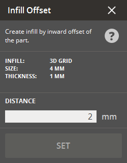
To apply an inward offset:
Under the Parts List a new group will be created containing the part and infill.

Wall Thickness Reduction - Wall thickness is set by the distance value when applying an inward offset and has the greatest effect on cost and weight reduction of your part. Generally, you should avoid wall thicknesses less than 1mm. Exceptions include small parts, parts with higher infill density, parts where weight reduction is paramount. You can also make up for a thinner wall by selecting a higher density infill pattern. It is often more efficient to use extra material in an infill pattern rather than thickening the shell to achieve part strength and rigidity.
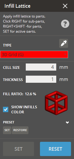
The Lattice command can be used to apply a selected infill geometry to an inner offset or to an entire part.
The three patterns available in 3D Sprint, in order of increasing relative density, are Grid < Jacks < Star (at same cell size, thickness). Auto Support and Solid Build are also available and offer a hollow (no infill lattice) or solid part respectively.
Lowering infill density will decrease part cost/weight, and improve wax drain-ability. Too low of an infill density will not provide part rigidity. Cell size and rod thickness will be determined on a part-by-part basis. In general, Infill densities of 25% or less drain well.
To apply a lattice:
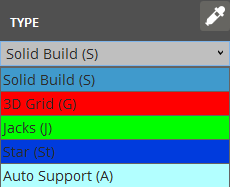
Note: The ProJet 2500 IC also has access to the Cellular Structure (CS) lattice type.
Enter the desired Cell Size and Thickness
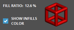
Note: When a lattice type is selected, a preview of the
lattice can be seen in the lattice command window showing the Fill Ratio.
A preview of the infill lattice is also shown next to the
part in the main window.
To apply a preset lattice to the Offset command:
Enter the desired Cell Size and Thickness.
Under the Preset section, click Set.

The preset for Infill > Offset will now be the default lattice.

Cell Size - After the user applies “infill offset” to the part, they can measure the core thickness. We recommend that the cell size should be less than or equal to the thickness of the infilled part, but greater than 3 mm. With Jacks and Star patterns, the cell size should be 4 mm at the minimum to ensure drainage.
Thickness - After cell size is chosen, the user should set the thickness (of the lattice "bars"). The thickness should be greater than .75mm to maintain rigidity. You will need to keep an eye out for infill density as you adjust thickness. If the infill density exceeds 25% or the user’s expectation, the user should select a lower density pattern, or increase the cell size. If the cell size is already at a minimum, then the part may not be suitable for an infill pattern or the pattern will not connect in three axes.
Vent Drain in the Infill toolset is a new command that allows easy click-to-place designation of holes with diameter and depth specified by the user. This is achieved using a cylinder primitive to perform virtual Boolean subtraction.
Vent/drain holes should be added to a part to prevent thermal expansion of the internal support material and allow drainage. Smart placement of the vent/drain holes will make for easy post processing. Infilled parts come out of the printer filled with wax that must be melted and drained to prevent deformation in post processing.
Place the holes at extreme corners where all the cavities of the part converge to ensure easy drainage. At least two holes are needed: a vent and a drain. Set the depth of the holes about 2 mm greater than the shell thickness to prevent the infill pattern from covering drain hole. We recommend holes that are at least 3mm in diameter; larger holes will allow easier drainage.
To place vents or drains:
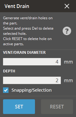
Under Infill, click Vent Drain.
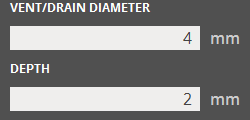
Enter a vent / drain diameter and depth in the parameters.
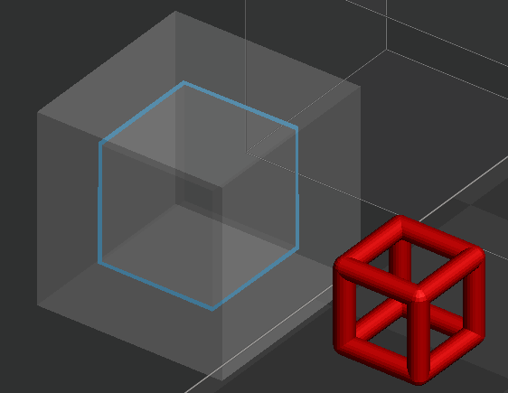
Position the mouse pointer over a part to see a preview of the size.
To place a vent or drain, click on the part. Vents
and drains can be placed on any location and are not constrained to
any particular orientation.
After placing, a preview will show position of the vent or drain in
white.
To place another vent or drain, click on the part again.
When all vents and drains are placed, click Set.
Vents and drains will be visible on the part as a light colored circle once set.
To modify existing vents or drains:
Click on the desired part to be modified in the main window
Under Infill, click Vent Drain.
To modify a Vent Drain hole, click on the hole and drag it to a new location. Or, click on the hole to highlight it, then change the Diameter and/or Depth parameters and click Set.
To delete a Vent Drain hole, click on the hole in the part to highlight it, and then press the delete key.
To delete all Vent Drain holes on the part, click on Reset.
See Also