Supported Printers:
SLS-printers
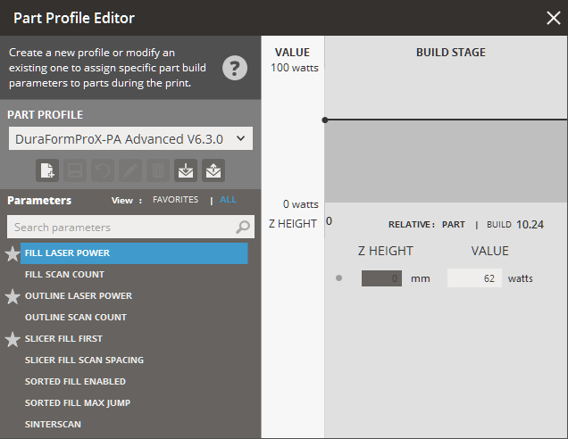
By default, the Part Profile assigned is defined during the configuration of printer and materials when setting up printer in the Printer command. However the Part Profile Editor allows you to create a new profile or modify an existing one to assign specific part build parameters to parts to define the behavior of the build at various Z levels during the print. Part Profiles can be assigned to selected parts of a print build. You set part parameters and create part profiles with the Part Profile Editor, launched from the Print tab.
Please see How Parameters Work for a more general overview of parameters.
Loading and Saving Profiles
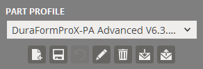
Part Profiles can be saved and loaded in the Part Profile Editor.
To load a saved part profile:
Click Import ![]() .
.
Select a part profile file stored on the local machine.
Once the part profile has been loaded you can select it from the Part Profile drop-down list to apply it.
To export a saved part profile:
Select a part profile to export from the drop-down.
Click Export ![]() .
.
Choose a location, name the output file and click save.
To create a new part profile :
Enter the values for each parameter.
Click New ![]() .
.
Enter a name for the Part Profile.
To update a part profile:
Select a part profile from the drop-down.
Enter the values for each parameter.
Click Update ![]() .
.
If necessary, click Rename ![]() to rename the selected part profile and then change to a new name
in the Name box.
to rename the selected part profile and then change to a new name
in the Name box.
To delete a part profile:
Select a part profile from the drop-down.
Click Delete ![]() .
.
To restore part profile to the default values:
Click Restore ![]() .
.
Click OK on the dialog box.
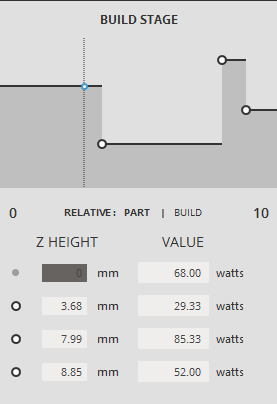
Build Stage
|
For each parameter, you can tell the system what values to use at various Z levels during the stage of the build; this is called a profile. You can click to create a point on each stage to create a row in the table for the each Z height when the parameter should change. The values of points can be changed by either modifying the values below the graph or by clicking and dragging the points on the graph. To delete a point, select it by clicking it on the graph and press delete from the popup dialogue. If you intend for a parameter to use the same value throughout a build, its table should have only one row, with a Z height of 0.000 and the desired value. |
Part Profile Parameters
The complete set of parameter can be viewed by selecting ALL under parameters. SIMPLE show the most commonly used values.
Please see How Parameters Work for a more general overview of parameters.
Outline Outside Contour Only - If Outline Scan Count is not set to zero and Outline Outside Contour Only is set to 1, outline scans are restricted to outside contours only. 0 is Off; 1 is On. Upward/Downward Fill Compensation - Automatically decreases scan spacing and adjusts Fill Laser Power when scanning layers that include up- or down-facing horizontal (or near horizontal) surfaces. Sorted Fill will be automatically turned off for these layers as well. This improves horizontal surface quality with negligible increase in build time. 0 is Off; 1 is On. The Upward/Downward Fill Compensation parameter is off by default. However, you can switch it on/off at specified part heights. The layers scanned with decreased scan spacing can be seen in Preview, if the zoom level is sufficiently high. Fill Laser Power - The amount of laser power (in watts) that will be delivered to the part bed, when the laser is filling in a slice or outlining a slice, respectively. You should adjust these parameters when you want to change power input to the part. Fill Scan Count - The number of times the laser scans the same cross-section without additional powder being laid, with a maximum of 10 times. Entering a zero for either value disables scanning. Outline Laser Power - The amount of laser power (in watts) that will be delivered to the part bed, when the laser is filling in a slice or outlining a slice, respectively. You should adjust these parameters when you want to change power input to the part. Outline Scan Count - The number of times the laser scans the same cross-section without additional powder being laid, with a maximum of 10 times. Entering a zero for either value disables scanning. Slicer Fill First - Automatically decreases scan spacing and adjusts Fill Laser Power when scanning layers that include up- or down-facing horizontal (or near horizontal) surfaces. Sorted Fill will be automatically turned off for these layers as well. This improves horizontal surface quality with negligible increase in build time. 0 is Off; 1 is On. Slicer Fill Scan Spacing - The distance between parallel scans during a fill. Shorter distances provide more laser energy. If the scan distance is too great, the cross-section may not be completely sintered. Sorted Fill Enabled - This parameter causes some parts to scan faster by reducing the average jump length during scanning. A value of 1 turns the feature on; 0 turns it off. Sorted Fill Max Jump is a related parameter. Sorted Fill Max Jump - This advanced part parameter is the maximum jump length before the sorter sorts the vectors into a different group. The default is 0.5 inch (12.7 mm). 3D Systems recommends that you do not change this value. If you decrease the value, it increases the number of temporary files the system creates and increases the computer processing time. If you increase the value, you decrease the number of temporary files and computer processing time, but increase the scan time. SinterScan - An advanced parameter which requires a license to be installed for sPro model printers. It alternates the scanning direction every layer, switching from X to Y each time. This parameter is only available with certain materials. Outline Outside Contours Only - If Outline Scan Count is not set to zero and Outline Outside Contour Only is set to 1, outline scans are restricted to outside contours only. 0 is Off; 1 is On. This advanced part parameter is only available only for DuraForm PA and DuraForm GF materials. |
See Also