Supported Printers:
SLA-printers
Supported Printers:
Figure 4 printers
NextDent 5100
Customize support parameters as required.
Note: Features marked
with a ![]() are only available with a 3D Sprint Pro License.
are only available with a 3D Sprint Pro License.
Find Must Watch - Best Practices at the following link:
http://infocenter.3dsystems.com/videolibrary/figure-4-training-videos
Proceed to one of the following topics for more information:
The following explains in detail all the parameters found in the Analyze tab for generating support anchor points using the Smart Support tool.
Anchor Points designate the locations where a support structure is necessary and will connect to the part. Generally, the part is analyzed to determine unsupported regions, followed by a propagation of Anchor Points in those areas. Determination of the unsupported regions, as well as behavior of anchor point propagation, are adjustable through user parameters.
Anchor Points can be broadly classified into three types: Contour Points, created along part boundaries, Inner Points, supporting faces, and Additional Points, support points that consider special process requirements such as balancing and stability.
In the event of geometry qualifying for multiple criteria, priority of points generated is generally as follows:
Primary Region Point, Point Region, Line Region - With this category of behaviors, you are generally defining preferences for downfacing planes, the sensitivity towards continuous sloping geometry, overhang regions, and critical regions such as locally low points and lines.
COM, Recoat Point - These types of points are meant to address any balancing and force-resisting requirements.
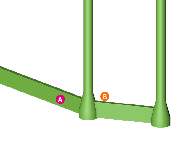
Thin Wall, Extra Near-Flat - Additional point distributions driven by detectable mesh conditions. Thin Wall describes any geometry where the wall thickness falls below a specified threshold. Extra Near-Flat describes downfacing areas of very slight curvature, which, although they are not strictly point or line regions, may need points to reinforce the critical area.
Curve Face - Additional point distributions driven by detectable mesh conditions. Curve Face describes geometry, such as radii and fillets, at or above a specified curvature intensity.
Sharp Edge - Additional point distribution driven by detectable mesh conditions. Sharp Edge describes prismatic edges, such as those typically created by CAD design workflows.
Extra Wall Point - Additional point distributions driven by detectable mesh conditions. Extra Wall Points distribute additional anchor points along the projected XY grid of all present anchor points. If the distribution would otherwise fall below a specified interval, an Extra Wall Points are added.
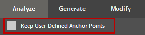
Note: To keep the user-defined parameters for anchor points, select the Keep User Defined Anchor Points checkbox.
The following parameters are available in the Analyze tab:
|
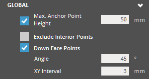
Max. Anchor Point Height (Min. 3mm - Max. 500mm) - Specify the maximum Z-height for anchor points. Anchor points will not be generated above the specified Z-height. Exclude Interior Points - Allows to add voids to no-support lists and prevent from generating supports on the inside of parts. Exclude Gap Clearance (Min. 0.1mm - Max. 10mm) - Allows to remove anchors in conformal cooling channels and other small features. Max. Drain Diameter (Min. 0.1mm - Max. 20mm) - Specify the maximum diameter drain threshold. Down Face Points - Generates more anchor points to geometry below the mesh down face angle threshold and is applied globally. Angle (Min. 0° - Max. 90°) - Specify the downface identification angle for surfaces to be eligible to receive Thin Wall Points. Downface angle is measured between the face normal vector and negative Z-axis. Under 90 degrees, only faces with normal vector slightly deflected from the -Z axis are eligible for Down Face Points. At 90 degrees, most walls are eligible for Down Face Points even if perpendicular to the XY plane. XY Interval (Min. 0.25mm - Max. 25mm) - Specify the interval of placement as distance in XY Projection. A small value populates Down Face Points densely on eligible surfaces. A large value populates Down Face Points sparsely on eligible surfaces. |
||||
|
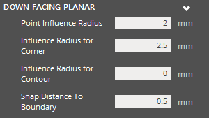
Point Influence Radius (Min. 0.25mm - Max. 25mm) - The radius a single inner anchor point can support in the same layer, but does not address point density along boundary or corner case. A smaller value will result in a higher density of inner anchor points and a larger value will result in a sparser density of inner anchor points. Influence Radius for Corner (Min. 0.25mm - Max. 25mm) - The radius one anchor point can be considered to be supported from corner points in the same layer. Applicable to the interior of acute angles at edges. A smaller offsetting value allows the corner point to be nearer the corner edge and a larger value offsets the points farther from the corner edge. Influence Radius for Contour (Min. 0mm) - The radius one anchor point can be considered to be supported from contour points (excluding corner points). A smaller offsetting value allows the contour point to be nearer the contour edge and a larger value offsets the points farther from the contour edge. Snap Distance to Boundary (Min. 0mm - Max. 1mm) - The distance of anchor point to boundary, which defines the edge offset feature. When the value is 0, points would be directly on the boundary. For values greater than 0 the points are inset by the value.
|
||||
|
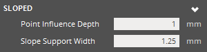
Point Influence Depth (Min. 0mm) - Specifies the z-depth that can be influenced by an anchor point. Inside of this range, Point Influence Radius is enforced. At small values more anchor points are generated in the slope case. At large values less anchor points are generated in the slope case. Slope Support Width (Min. 0.01mm - Max. 2mm) - The radius of range where the lower layer can support upper layer. A smaller value can cause more anchor points to be generated, and a larger value can cause less anchor points to be generated.
|
||||
|
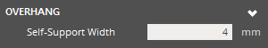
Self-Support Width (Min. 1mm - Max. 25mm) - The width where a layer can be self-supported by multiple layers printed beneath. A smaller value can cause more anchor points to be generated, and a larger value can cause less anchor points to be generated.
|
||||
|
Minimal Anchor Point Dis. - Specify horizontal (XY) distance requirement before introducing extra anchor points for balancing about the line or point region. When no other anchor point is added yet, at this threshold an anchor point is added. Extra Near-Flat Anchor Points - If enabled, near-flat regions can receive Extra Near-Flat Anchor Points in the nearby vicinity on the down facing convex. Solidify Bottom Layers - Flag to enable simulating the printing process by accumulating statistics layer by layer. It would enable add extra anchor points for bottom point/line regions, recoating force resisting. It also enables identifying bottom anchor points with a large weight on them. |
||||
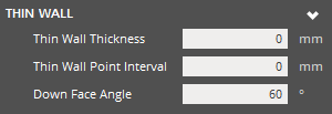 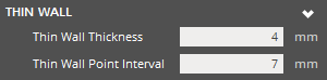 |
Thin Wall Thickness (Min. 0mm) - Specify the threshold of acceptable wall thickness. Geometry with thickness at or below the threshold are eligible to receive Thin Wall Points. Thin Wall Point Interval (Min. 0mm) - Specify the interval of Thin Wall Point placement as distance in XY Projection. Down Face Angle (Min. 0°) - Specify the down face identification angle for surfaces to be eligible to receive Thin Wall Points. Down face angle is measured between the face and negative Z-axis. |
||||
|
Curve Face Curvature (Min. 0) - The curvature threshold that must be surpassed for a region to be eligible for Curve Face Points. 'Curvature' is a value equal to 1/R where R = Radius of theoretical curvature. At 0, the detection of curvature is the most sensitive. Even planes are eligible for curve face points at 0 curvature value. Curve Face Anchor Point Interval (Min. 0mm) - The interval of Curve Face Point placement as distance in XY Projection. Small values create a high point density on eligible surfaces. Where a high values creates a sparse point density. Curve Face Down Face Angle (Min. 0°) - The downface identification angle for surfaces to be eligible to receive Curve Face Points. This is a traditional down face angle, measured between the per-face normal vector from -Z axis. Concave Curve Face Point - Enable this option to also allow Curve Face detection to work for concave regions. |
||||
|
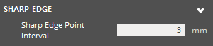
Sharp Edge Point Interval (Min. 0mm) - The interval of anchor point placement as a linear distance following the sharp edge. A smaller value will result in densely populated anchor points along edges. With a large values edges will be populated with anchor points.
Sharp Edge Down Face Angle (Min. 0°) - Angle to identify which edges require Sharp Edge Points. The specified threshold must be exceeded in order to generate sharp edge points to generate. Angle is measured between the edge normal and positive Z-axis.
|
||||
|
Recoating Points - Enables the existing parameters related to the recoating points.
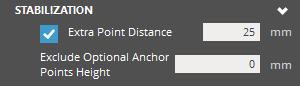
Extra Point Distance (Min. 3mm - Max. 100mm) - Specify XY-projected distance of extra anchor points. When no other anchor point is present, at this threshold an anchor point is added.
Trailing Edge Reinforcement - Used to identify the geometry of trailing or leading edges. Offset (Min. 0.5mm - Max. 100mm) - Creates anchor rows from the specified offset distance. Extra Rows (Min. 1 - Max. 4) - Adds extra anchor rows around the detected trailing edge regions. Use High Slope - Click to include high slope regions in the calculation when identifying the geometry of trailing or leading edges. Exclude Optional Anchor Points Height (Min. 0mm) - Optional anchor points above the given Z-height parameter are excluded. |
Support Width:
|
|
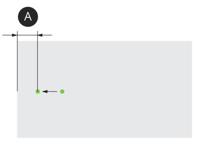
Snap Distance to Boundary:
|
|
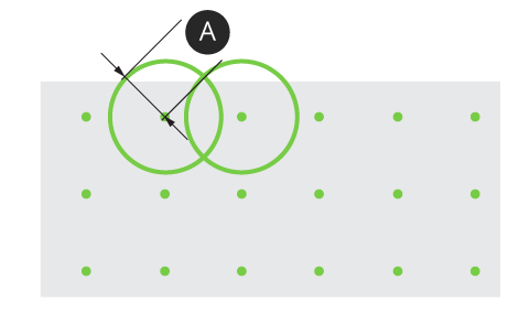
Point Influence Radius:
|
|
The following topic explains in detail all parameters when creating Empire supports when printing with an SLA printer.
Grid
Parameters of the generated support layout.
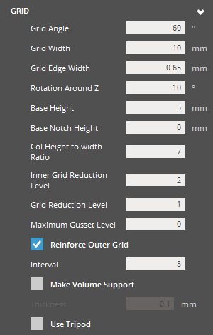 |
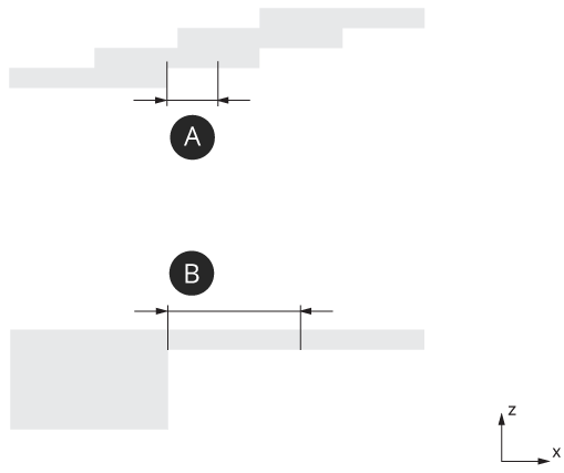
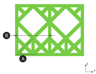
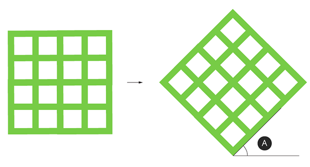
Grid Grid Angle (Min. 1° - Max. 89°) - The angle of the Grid's trusses measured from the XY plane. Along with the Grid Width, this parameter defines the dimensions of the grid. A smaller truss angle will be more acute, resulting in shorter grids. A larger truss angle will be less acute, resulting in taller grids. Grid Width (Min. 5.5mm - Max. 25mm) - The width that defines a single grid cell. Along with the Grid Angle this parameter defines the dimensions of the grid. A smaller value results in grids at a finer resolution. The approximation to the XY footprint of the part shape is more accurate. More vertices will exist for connection structures to attach to and more support material is used. A larger value results in grids at a coarse resolution. The approximation to the XY footprint of the part shape is less accurate. Less vertices exist for connection structures to attach to and less support material is used.
With a smaller value grids have thinner, more hair-like beams, although in the printing process the true laser spot size dictates a minimum feasible thickness and may result in bigger structures. With a larger value resulting grids have thicker beams in virtual representation and printing. Rotation Around Z (Min. 0° - Max. 90°)- The Grid's angle of alignment about the Z-axis. At 0 or 90 degrees, no rotation is present. Grid is aligned orthogonally to X and Y axis. Choose an angle where 0 < angle < 90 for a rotation effect. Base Height (Min. 2mm - Max. 50mm) - Specify the height of the Grid Base structure, which can be independent of the grid cell height. The width of the Grid Base Structure is equivalent to Grid Width. A smaller value will result in a short base structure and a larger value will result in a tall base structure. Base Notch Height (Min. 0mm - Max. 50mm) - Specify the height of a base notch at the outer edge. 0 is for no notch. Col Height to Width Ratio (Min. 3 - Max. 30) - The behavior of growth in grid columns to reinforce tall structures. Specify the threshold as a ratio of (Grids in column height / Grids in column width). When the threshold is exceeded, lower portions of the grid column grow wider. At a small value, the column will not have to be very tall in order to observe some growth of the grid structure. At a large value, the column will have to be very tall in order to observe some growth of the grid structure.
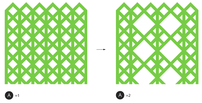
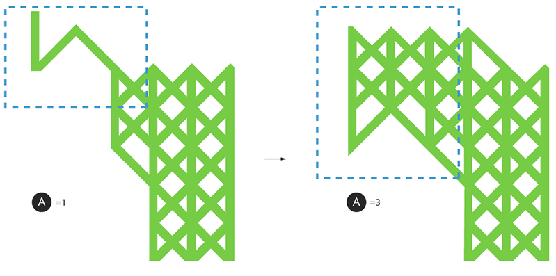
Grid Reduction Level (Min. 1) - Reduces the overall amount of trusses used in the support structure. Minimum value of 1. Maximum Gusset Level (Min. 0) - The maximum possible length of gusset structures in terms of (input * Grid Width ) At a smaller value only very small or short gusset structures can be generated. At a larger value longer gusset structures can be generated. Active Slope Control - Creates less cantilevered support over regions of an up-facing slope. It’s advantageous for the part-part support connections on the slope. Reinforce Outer Grid - Toggle option to enable or disable the Reinforce Outer Grid behavior. This behavior will prevent reduction of trusses at the Reinforce Outer Grid - Interval value by maintaining the original grids, thus ignoring effects of Grid Reduction Level. Interval (Min. 1) - The threshold of Reinforce Outer Grid as an interval. At Interval = 1, minimal reduction occurs because most of the original grid is maintained. At an arbitrarily large Interval value, reinforcement may not have much effect on the otherwise expected degree of reduction. Can result in longer trusses. Make Volume Support - Allows the increase of the volume of the support structure. Thickness (Min. 0.01mm) - If Make Volume Support is enabled, specify the desired thickness of support mesh beams. The resulting beam is defined by Grid Edge Width and projected by extrusion amount equivalent to Thickness. This option is available when the Make Volume Support option is selected. Strong Support Thickness (Min. 0.01mm - Max. 1mm) - Specify the thickness of closed volume (Strong) supports. Strong Support Spread (Min. 1 - Max. 16) - Specify the spread range for closed volume supports. Use Tripod - Enables trussing routine for long bottom connections or reinforces tall pillar using nearby sidewall. |
|
|
Rotation around Z:
|
Rotation around Z |
Support Base:
|
|
Col Height to Width Ratio:
|
|
||||||
Grid Reduction:
|
Grid Reduction Level |
Gusset:
|
Maximum Gusset Level |
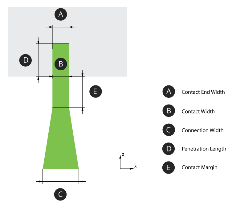
Top Connection
The structure of the generated support:
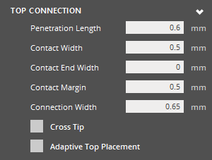 |
Top Connection Penetration Length (Min. 0.01mm) - The distance that the support tip intersects with the object. From the nominal surface, positive values are inwards (opposite the direction of surface normal). Negative values are outwards (along the direction of the surface normal). At a smaller value the section of tip that is to intersect the object is short. Due to the layer thickness voxelization that is applied when the object is analyzed, an inadequately short tip may not be robust to voxelization errors and fail to intersect the part. At a larger value the section of tip that is meant to intersect the object is long. This will be robust to errors that can be imposed by layer thickness voxelization. Potentially, a long tip could exceed a thin wall thickness. Contact Width (Min. 0.001mm) - The width of the support tip at the base of the tip cone. Values smaller than the Contact End Width will result in a suboptimal tip shape (trapezoid with long edge oriented towards +Z) Contact End Width (Min. 0mm) - The width of the support tip at the end of the tip cone. Values larger than the Contact Width will result in a suboptimal tip shape (trapezoid with long edge oriented towards +Z). Contact Margin (Min. 0.001mm) - The length of the tip structure maintained as a margin outside of the object. Without adequate clearance and tip length, the Connection Width could unintentionally define the true intersection surface area. Connection Width (Min. 0.001mm) - The width of the intermediate structure that serves as the interface between tip and grid. Cross Tip - Toggle option. When enabled, use a full-cross shape tip. Leave disabled to use a default half-cross shape. Adaptive Top Placement - Allows the top connection to originate anywhere on the top of a grid, rather than being constrained to only the vertices, to make the top connections more vertically on average. Anchor Clearance (Min. 5mm - Max. 50mm) - Specify the anchor clearance for top supports. Rel. Grid Clearance (Min. 0.2 - Max. 0.9) - Specify the relative anchor grid clearance for top supports. Use Half-Grid Connection - Click to use half-grid connection for top supports. Angle (Min. 10° - Max. 80°) - Specify the angle of half-grid connection for top supports. Rel. Clearance (Min. 0.5 - Max. 0.9) - Specify the relative anchor grid clearance of the half-grid connection for top supports. |
|
|
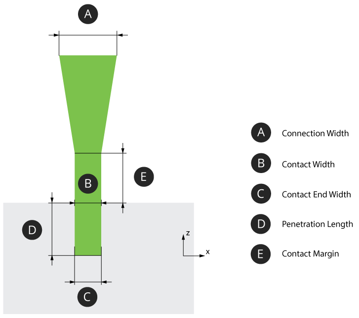
Bottom Connection
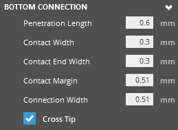 |
Bottom Connection Penetration Length (Min. 0.01mm) - The distance that the support tip intersects with the object. From the nominal surface, positive values are inwards (opposite the direction of surface normal). Negative values are outwards (along the direction of the surface normal). At a smaller value the section of tip that is to intersect the object is short. Due to the layer thickness voxelization that is applied when the object is analyzed, an inadequately short tip may not be robust to voxelization errors and fail to intersect the part. At a larger value the section of tip that is meant to intersect the object is long. This will be robust to errors that can be imposed by layer thickness voxelization. Potentially, a long tip could exceed a thin wall thickness. Contact Width (Min. 0.001mm) - The width of the support tip at the base of the tip cone. Values smaller than the Contact End Width will result in a suboptimal tip shape (trapezoid with long edge oriented towards +Z) Contact End Width (Min. 0mm) - The width of the support tip at the end of the tip cone. Values larger than the Contact Width will result in a suboptimal tip shape (trapezoid with long edge oriented towards +Z). Contact Margin (Min. 0.001mm) - The length of the tip structure maintained as a margin outside of the object. Without adequate clearance and tip length, the Connection Width could unintentionally define the true intersection surface area. Connection Width (Min. 0.001mm) - The width of the intermediate structure that serves as the interface between tip and grid. Cross Tip - Toggle option. When enabled, use a full-cross shape tip. Leave disabled to use a default half-cross shape. |
|
|
The following topic explains in detail all parameters when creating Gate supports when printing with a Figure 4 printer.
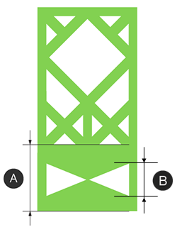
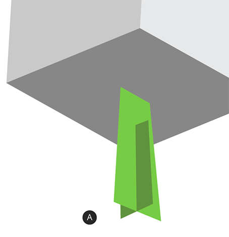
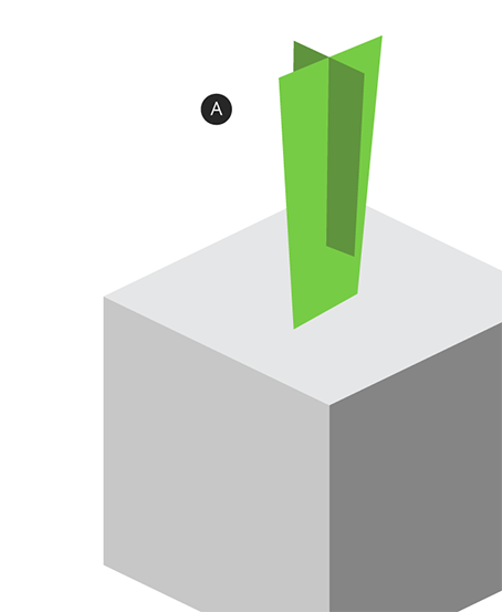
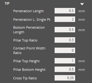
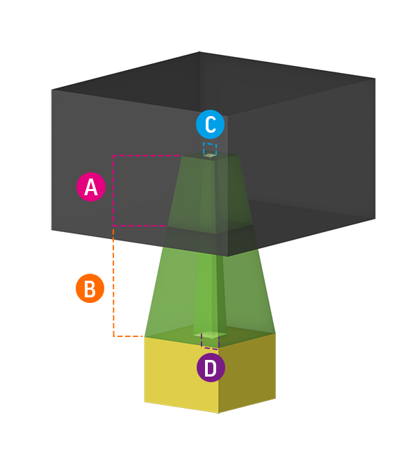
Tip
The portion of the support structure that touches or even intersects the part surface.
|
Tip Penetration Length - Controls the offset the tip in relation to the part. Note that this is the maximal length. For a thin part the penetration should be less than thickness of the part. At a negative value, the tip will be exterior to the part surface. At 0, the tip is in contact with the part surface. And at a positive value, the tip will be in the interior of the part surface. Penetration L. Single Pt. - Specify the magnitude of intersection in the case of single-point regions (like the tip of an upside-down pyramid). Bottom Penetration Length - Controls the offset of the bottom penetration length when pillars attach to a part like the Penetration Length above. Pillar Top Ratio - Ratio between the pillar and the radius of the top of the tip. In the case of a cross tip it would specify the length of a single arm. Contact Point Width Ratio - Specify tip width at the middle of the tip, as a ratio of the trunk pillar width. This is the width where the intersection of the tip and part nominal surface occurs. The Cross Tip Ratio will be ignored if this parameter is used. Pillar Top Height - Controls the maximum length of the tip outside the part. Pillar Bottom Height - Controls the maximum length of the base of the pillar. Cross Tip Ratio - Ratio that specifies the width of the cross tip at the top of the tip structure compared to the pillar trunk width. |
|
|
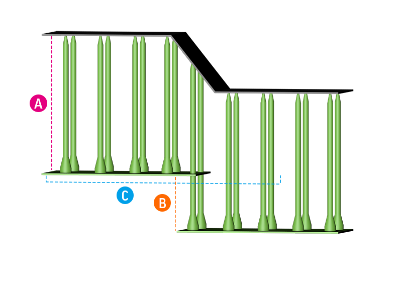
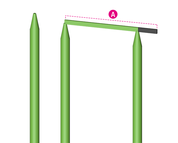
Bridge
The bridge is a horizontal structure that supports a line of grouped pillars or anchor points above it. Since pillars are not always required underneath the bridge for sufficient supporting, this can be modified to reduce material and print time requirements.
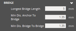 |
Bridge Longest Bridge Length - Maximum allowable length of a bridge. With a small value, only short bridges may be allowed seeing less bridges and more pillars in some cases. A large value will see the creation of more and longer bridges with less pillars. Minimum Distance Anchor to Bridge - Minimum z height of a anchor point to a bridge. This is related to the searching z height of bridges. With a small value, bridge structures will be created closer to the anchor points. Large values will have a bigger distance between the bridge structure and the anchor points. Minimum Distance Bridge to Bridge - Minimum z height of a bridge to another bridge. If this is equal to minimal distance anchor point to bridge, this adds more searching options to bridges, thus slows down the performance. If it is equal to minimal distance anchor point to bridge, the performance is better. |
|
||||||
|
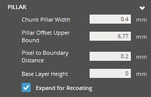
Pillar
The pillar is the portion of the structure that raises vertically, and is the primary structure between the platform and part.
|
Pillar Chunk Pillar Width - Defines the initial width of the pillars. Pillar Offset Upper Bound - Specify the upper limit of additional offsetting achievable from Longest Point Offset. The additional offset allowance occurs if the anchor point is supported by part or platform. Pixel to Boundary Distance - Specify the minimum distance between any pillar and any part that it may be near. A positive value is advantageous in order to accommodate for material expansion and precision level. Base Layer Height - Number of base cylindrical parts of a pillar, specifying the height. Expand for Recoating - Enable to allow expansion of pillars in the direction of recoating action. |
|
|
Truss
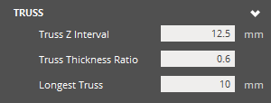 |
Truss Truss Z Interval - Set the z interval/spacing for trusses along a pillar. At a smaller value on pillars of considerable height, more trusses are generated. At a larger value on pillars of considerable height, less trusses are generated. Truss Thickness Ratio - Specify the thickness of trusses as a ratio of the pillar trunk width. Longest Truss - Maximum truss length. With a small value and a reasonable distribution of pillars, fewer trusses are created as they do not successfully fall under the threshold. With a larger value, more trusses will be created. |
|
|
Base Truss
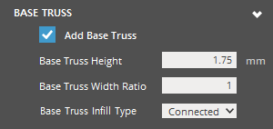 |
Base Truss Add Base Truss - Check to create a base truss. Base Truss Height - The maximum Z-height of the Base Truss structure. Base Truss Width Ratio - Specify the thickness of base trusses as a ratio of the pillar trunk width. Values change the thickness of the bass truss structure relative to the pillar structures. Base Truss Infill Type - Infill type for base truss. This saves material and makes it easier when removing supports from the platform. |
|
|