 Build Style (Figure 4)
Supported Printers:
-
Figure 4 printers
Build Styles are parameters that control the slicing 3D Sprints software does to your parts. Style consist of information on the type of Figure 4 setup upon which you intend to build your parts, the style of build you will be executing, and the best parameters for successful part building. Styles for part regions and the base layer are assigned separately.
Build Styles are initially assigned to an entire Print Platform based on the Printer configuration and can then be changed with the Build Style command. Once assigned, you can change the style preset, edit the build parameters in the style preset, or add a different style preset to a particular range of a part.
Styles are assigned to the entire print build.
Note: (NextDent 5100 Printer) Click Simple UI ![]() to switch between the simple and the advanced User Interface. In the Simple UI, only the tools for minimum workflow are visible.
to switch between the simple and the advanced User Interface. In the Simple UI, only the tools for minimum workflow are visible.
Add a Build Style
To add a build style,
-
Select a Build Style from the Print tab.

-
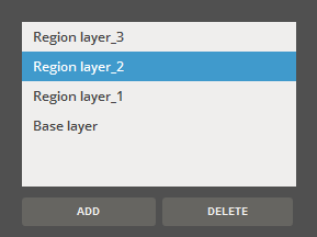
Under the Advanced, select the default region or base layer, or use the Add or Delete buttons to create a new layer, or delete the selected layer.
-
Modify the size or parameter for a selected layer.
Note: There are also Global parameter available that are applied to the entire build.
-
Click Apply to apply the style.
Editing Build Style Parameters.
Why edit Build Style Parameters? Parameter editing may be deemed necessary to accommodate a specific combination of part geometry, resin, and build style. In an effort to provide a system that helps direct users toward successful part building, the build style parameters incorporated into the 3D Sprint application contain optimized parameters for building high-quality parts. These presets exist for every Figure 4 model/resin combination currently available.
Global parameter for X/Y Offset and Scaling Factor X/Y can be calculated using the Accuracy Wizard. Start the wizard by clicking the ![]() icon.
icon.
Build Style Parameters by Printer
|
|
NextDent 5100 for Ceramill |
NextDent 5100 |
Figure 4 Standalone / Modular / Jewelry |
|---|---|---|---|
|
Region Layer Layer Parameters |
Layer Thickness Cure Depth Layer Speed Interval Line Interval Distance Interval Up Time Interval Pause Time Interval Down Time Interval Down Pause Time Z-Compensation |
Cure Depth Layer Speed Interval Up Time Interval Down Pause Time Z-Compensation |
Layer Thickness Cure Depth Layer Speed Interval Line Interval Distance Interval Up Time Interval Pause Time Interval Down Time Interval Down Pause Time Z-Compensation Small Feature Width Small Feature Preservation |
|
Base Layer Parameters |
Number of Base Cure Layers Base Layer Thickness Base Layer Curing Time |
||
|
Global Parameters |
X/Y Offset Minimum Support Height Scaling Factor X ,Y,Z Support Cure Depth Support Tip Cure Depth |
X/Y Offset Minimum Support Height Scaling Factor X ,Y,Z Support Cure Depth Support Tip Cure Depth |
Border Thickness X/Y Offset Minimum Support Height Scaling Factor X ,Y,Z Support Cure Depth Support Tip Cure Depth Drain Duration (Only for Figure 4 Modular) Drain Height (Only for Figure 4 Modular) |
Parameter Description
Region Layer Parameters
Layer Thickness (Min. 1μm) - Sets the thickness for region layers.
Cure Depth - Sets the depth of the curing in a region layer.
Layer Speed - The velocity at which the elevator moves to cure each layer in inches or millimeters per second.
Interval Line - Increment for larger up motion between cure layers for material refresh. If interval line=n, build will move higher every nth layer. This allows for better refill of resin at the film.
Interval Distance - The distance the elevator moves up/away from the film at each Interval line increment.
Interval Up Time - The time it takes for the elevator to move up the interval distance.
Interval Pause Time - After the elevator moves up the interval distance, this is the time it will then wait before moving the elevator back down towards the film at each Interval line increment.
Interval Down Time - The time it takes for the elevator to move back down towards the film.
Interval Down Pause Time - After the elevator move down the interval distance, this is the time it will then wait before moving the elevator back down towards the film at each Interval line increment.
Z-Compensation - Sets the compensation in the Z direction.
Small Feature Width - Defines the minimum XY feature size that flags an area as a small feature. This area will see a feature size increase set by the small feature width value.
Small Feature Preservation - Turns on small feature preservation routine for parts in the build.
Thin Feature Preservation - Select to retain thin features against greater Z Compensation.
Base Layer Parameters
Number of Base (Cure) Layers - Sets the maximum number of base (curing) layers.
Base Layer Thickness - Sets the maximum thickness of the base layers.
Base Layer Curing Time - Sets the curing time for the base layers.
Global Parameters
Border Thickness (Min. 0mm - Max. 120mm) - The layer thickness to which the layer borders are created.
X/Y Offset (Min. -1mm - Max. 1mm) - Sets an offset distance along the X/Y axis.
Cure Depth - Sets the depth of the curing in a region layer.
Minimum Support Height (Min. 0mm - Max. 120mm) - The minimum height for generating supports.
Scaling Factor X ,Y, Z (Min. 95% - Max. 105%) - Sets the scaling factor in the X, Y or Z access
Support Cure Depth - The measurement depth of the support cure.
Support Tip Cure Depth - The measurement depth of the support tip cure.
Drain Duration (Min. 0sec - Max. 1,000,000sec) - Sets the maximum duration of resin drainage. This option is available only for Figure 4 Modular.
Drain Height (Min. 0mm - Max. 344,923mm (13.58in)) - Sets the maximum height of resin drainage. This option is available only for Figure 4 Modular.
Note: The Drain Duration and Drain Height options prevent resin from spilling outside of the resin tray in the print engine chamber so that printer does not get disturbed by strings of dripping materials when the completed job print tray is moved to its origin position.
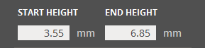
Resize a Layer
To resize a region, drag the top or bottom plane.
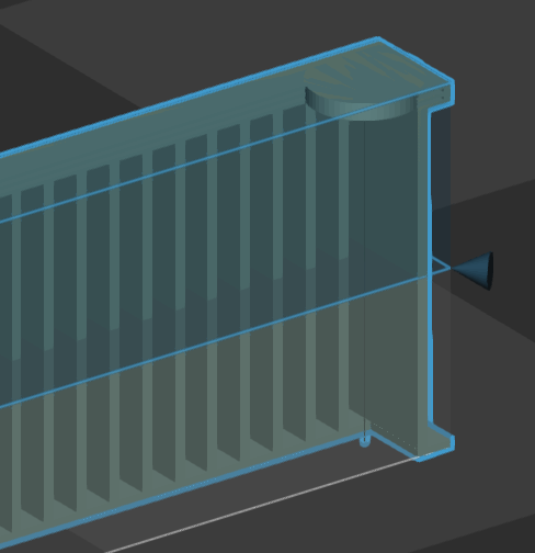
Or enter the start / end height in the command panel.
Remove a Layer
To remove a layer, select it and then click Delete.
Loading and Saving Profiles
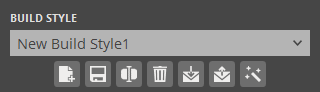
Build Style presets can be saved and loaded in the Build Style command.
Note: Build Styles presets for Figure 4 printers are a combined set of region styles. They are not saved as separate regions as is done for SLA printers.
To load a saved preset:
-
Click Import
 .
. -
Select a preset file stored on the local machine.
-
Once the preset has been loaded, you can select it from the Region Style preset drop-down list to apply it.
To export a saved preset:
-
Select a preset to export from the drop-down.
-
Click Export
 .
. -
Choose a location, name the output file and click save.
To create a new preset:
-
Enter the values for each parameter.
-
Click New
 .
. -
Enter a name for the Region Style preset.
To update a preset:
-
Select a preset from the drop-down.
-
Enter the values for each parameter.
-
Click Update
 .
. -
If necessary, click Rename
 to rename the selected preset and then change to a new name in the Name box.
Note: Default presets can only be changed and saved as a new preset.
To delete a preset:
-
Select a preset from the drop-down.
-
Click Delete
 .
.
To calculate the optimal scales and offset parameters:
-
Select a preset from the drop-down.
-
Click Scale & Offset Wizard
 .
.
See Also