
 Color Map
The Color Map command allows you to assign predefined color maps to individual parts.
These maps allow for the mapping of a wide range of colors to existing or specialized material mixes, depending on their intensity. For example, you can define your own material mixes to convert input part color (typically texture) into material mixes for basic two-color support on printers like the ProJet 5500X-E/5600 for part/support mixtures.
To Apply A Color Map
-
Select part to apply the color map.
-
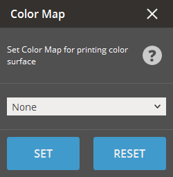
Click the Color Map command.
-
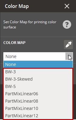
Select a predefined color map in the dialog.
-
Press Set to apply the color map or Reset to clear the changes.
To Customize a Color Map
-
Browse the sample color maps stored in the res/material/<Printer Name> directory within the default installation path. These maps are in the slicer XML format and have the form *.colormap.xml.
-
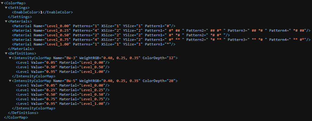
Modify or create new color maps based on existing files. You can adjust key parameters such as WeightRGB (translation of RGB color to intensity), ColorDepth (number of z-layers dedicated to color), and Level (intensity value corresponding to a given material).
The following is an example color map.
-
Customize the color map by modifying existing parameter values or adding/removing levels to suit your requirements.
Tip: Within the color map file, you can specify your own custom pattern, such as in the 5level_12.colormap file, and reference it in the color map definition. Alternatively, you can use a standard mix pattern named PartMix{n}, as seen in the partmix_linear.colormap file.