 Holes and Vent Drain
Make vent or drain holes in the part, to drain material after printing. This command requires a hollow part.
Note: Features labeled with ![]() require a 3D Sprint Pro Subscription for access. For assistance, please reach out to our technical support team at http://www.3dsystems.com/support or contact your regional sales manager.
require a 3D Sprint Pro Subscription for access. For assistance, please reach out to our technical support team at http://www.3dsystems.com/support or contact your regional sales manager.
Note: Click Simple UI ![]() to switch between the simple and the advanced User Interface. In the Simple UI, only the tools for minimum workflow are visible.
to switch between the simple and the advanced User Interface. In the Simple UI, only the tools for minimum workflow are visible.
Note: The Vent Drain command is only available for parts using QuickCast materials and build styles.
-
In the Print tab, click Holes.
-
Check whether the current model is hollowed.
-
If the current model is not hollowed:
-
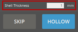
Select the part you want to hollow out and specify the desired shell thickness by entering a value in the Shell Thickness.
-
Click Hollow to apply the changes.
-
-
If the part is already hollowed, click Skip.
Note: Placing holes on a non-hollow part may lead to unexpected behavior.
-
-
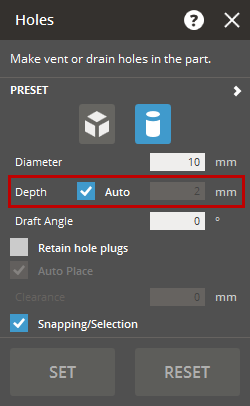
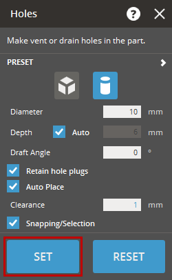
Select one of the hole types:
-
 Rectangular Hole - Length, Width, and Rotation require to be defined.
 -
 Round Hole - Diameter requires to be defined.
-
-
Select the Auto in the Depth option to allow automatic calculation of depth based on where you click on a part. To manually specify the depth of a hole, clear the Auto option and enter a value in the Depth option.
-
If necessary, define the daft angle for conical holes in the Draft Angle option.
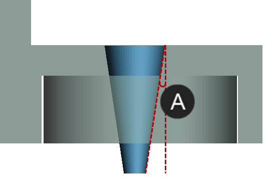

Draft Angle
-
Position the mouse pointer over the part to preview the hole's size.
-
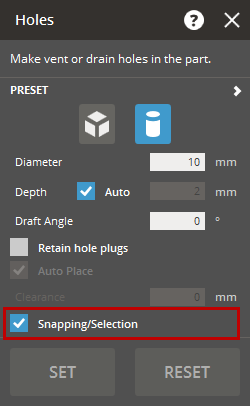
While the Snapping/Selection is enabled, you can snap the pointer to part faces or select existing holes.
-
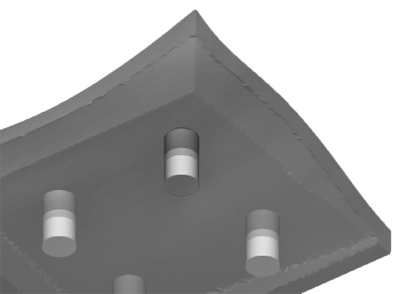
Click on the part to place the hole. The holes will be previewed on the part.
-
To remove a hole, select it and press Delete. To move a hole, select it and drag it to a new position on the part.
-
To place additional holes, click on the part again.
-
 To retain the hole plugs and print them separately from the part, click Retain Hole Plugs. The Auto Place enables you to quickly place created hole plugs onto the Print Platform.
Note: The Auto Place option is available when the Retain Hole Plugs is selected.
-
Set the Clearance to create space between the holes and the part, such as for glue or printing error.
Note: The Clearance option is available when the Retain Hole Plugs is selected.
Note: The clearance will cut into the holes reducing its size.
-
Ensure all holes are correctly placed, then click Set to accept the hole creation.
 Note: If the Retain Hole Plugs option is selected, the created hole plugs will be added as individual parts to the Parts List.
Note: The Vent Drain command will only be usable on parts using a QuickCast material and build style. Vents can only be placed on faces that are parallel to the Print Platform.
-
In the Print tab, click Vent Drain.
-
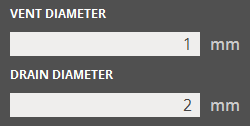
Enter a vent / drain size in the parameters. Position the mouse pointer over a part to see a preview of the size.
-
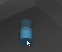
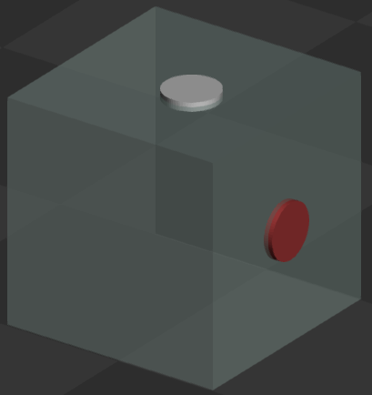
To place a vent or drain, click on the part. Vents in valid locations will show in blue, invalid locations will be in red.
After placing a preview will show position of the vent or drain in white.
-
To place another vent or drain, click on the part again.
Note: The Snapping/Selection option allows the snapping of the pointer to existing vent / drain holes. Click Snapping/Selection to easily select and move existing vent / drain holes.

-
When all vents and drains are placed, click Set.
Vents and drains will be visible on the part as a light colored circle once set.
- In the Print tab, click Vent Drain.
- Enter a vent / drain size in the parameters. Position the mouse pointer over a part to see a preview of the size.
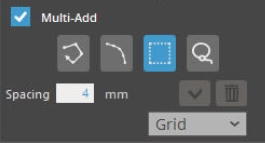
- Click on Multi-Add check box.
- When all vents and drains are placed, click Set.