 Smart Support
Supported Printers:
-
Figure 4 Printers
-
NextDent 5100
Supported Printers:
-
SLA-Printers
The Smart Support command allows the generation of a supporting structure to support parts during a build. Support structures function as scaffolding for the part during printing. The structures support the construction of parts and should be removed after the print is complete.
Note: Features labeled with ![]() require a 3D Sprint Pro Subscription for access. For assistance, please reach out to our technical support team at http://www.3dsystems.com/support or contact your regional sales manager.
require a 3D Sprint Pro Subscription for access. For assistance, please reach out to our technical support team at http://www.3dsystems.com/support or contact your regional sales manager.
IMPORTANT: It is strongly recommended that you combine parts before creating supports if they may be colliding or interlocked. See Combine / Separate for more information.
To Create supports and edit support parameters or import and export support parameter settings.
-
Select one or more parts to create supports.
-
To save or load support parameters, use the Style group.
-
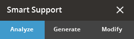
To only generate support anchor points, click Analyze.
-
To automatically create supports, go to the Generate tab and click Create.
-
To manually place supports, go to the Modify tab.
-
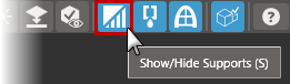
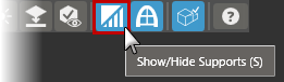
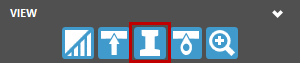
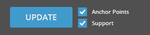
To view created supports and anchor points, toggle the Support and Anchor Points in the View group.


Note: The visibility of created supports can be toggled on and off by using the Show/Hide Supports button in the View Overlay found at the top corner of the working view.
-
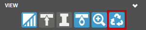
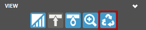
 To view created anchor points by type, use the By Type in the View group.
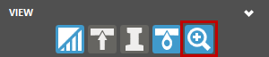

Note: The By Type option is available only when the Anchor Points option is enabled. Click HereHere to see a list of Anchor Point Types.
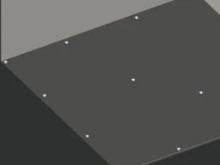
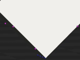
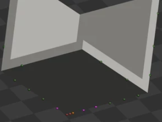
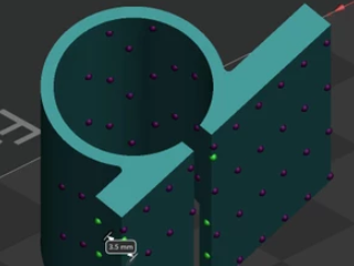
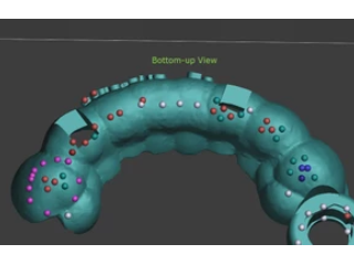
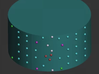
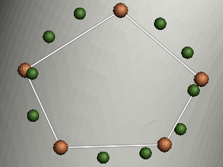
Enable this option to color-code all anchor points so that their origin can be understood.
Anchor Point Type
Color
Type
Example
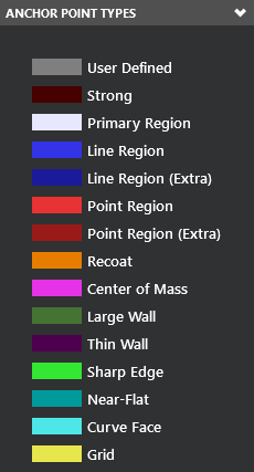
Dark Grey
User-defined (added manually)
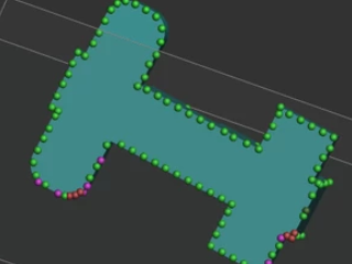
Reddish Purple
Strong
Light Grey
Primary Region Point
Light Blue
Line Region Points
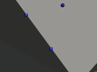
Dark Blue
Extra Line Region Points
Red
Point Region Points
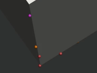
Dark Red
Extra Point Region Points
Orange
Recoating Points
Magenta
Center of Mass Points
Green
Extra Points for Large Wall
Dark Purple
Thin Wall Points
Bright Green
Sharp Edge Points
Teal
Extra Near- Flat Anchor Point
Aqua
Curve Face Point
-
After creating supports, the Unused Anchor Points button will appear if there are any unused anchor points. To view these points, toggle the Unused Anchor Points button in the View group. This option is available when Anchor Points option is enabled.
-
To view interface between the surface of the part and supports, toggle the Interface in the View group. This is available when the Support option is enabled.


-
To view strong Support structure, use the Strong Support in the View group.
-
When finished editing supports, click Close (X).
Auto Supports
Automatically create a support structure.
-
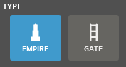
In the Generate tab, choose the Type.
-
Edit the parameters as required.
-
Click Create.
Generate Support Anchor Points
- Go to the Analyze tab
- Change the acquisition parameters.
- Click Create.
-
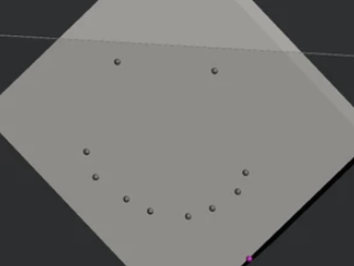
The support anchor points will now be displayed on the part, but no supports will be generated.
You can edit the anchor points, or the regions where the support is attached to the part.
Note: To move a point, click and drag the point to the desired position.
When satisfied, Exclude and click the detected region(s). The region is red when excluded correctly.
-
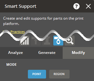
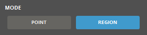
Go to the Modify tab, select Point to edit individual points or Region to edit an area of the part.
-
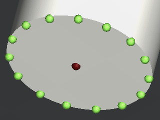
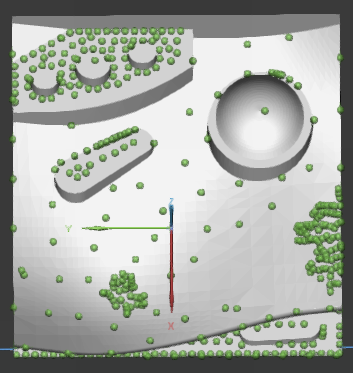
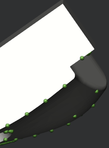
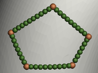
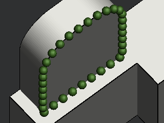
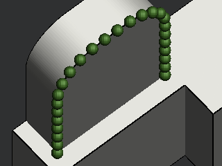
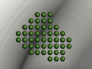
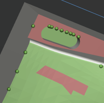
Anchor points can be seen as green balls on the part surface.
-
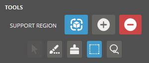
In the Modification Mode, click Add
 to add anchor points or click Erase
  to remove them.
 -
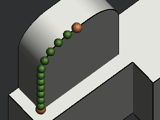
Select the Strong option to set the locations of anchors for closed volume supports inside the standard Empire support.
-
There are several selection tools to select region for creation or existing anchor points for deletion. Click Done
 to accept the selection or click Discard
  to cancel the selection.
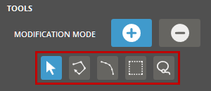
Note: Pressing the CTRL key inverts the current modification mode. For example, If Add is selected, the CTRL key switches the mode to Erase.
-
 Point - Click to add an anchor point on a part surface or select an existing point.
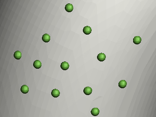
-
 Polyline (Only available in the Add mode) - Click to draw a polyline on a part surface. Set the Spacing for anchor points and strong anchor points, then create a polygonal area with straight lines on the part surface. Each click initiates a new line. Continue clicking to form a closed loop for a complete polygonal shape, or double-click to finish the selection. Anchor points are generated along the lines of the polygonal shape with the specified spacing.
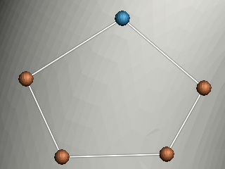
Note: To distribute anchor points on a virtual spline fitting to the vertices of the polygonal shape, click Fit.
-
 Edge (Only available in the Add mode) - Click to select a sharp edge of a part. Set the Spacing for anchor points and strong anchor points, as well as the Offset distance. Then, select a sharp edge of a part using one of these edge selection methods: Loop, Segment, or Start/End. Anchor points are generated along the chosen edge with the designated spacing. If an offset distance is specified, anchor points will be offset from the edge on the part surface.
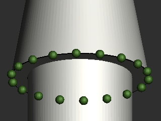
-
Loop - Finds a closed loop of an edge.
-
Segment - Selects a segment of an edge.
-
Start/End - Allows to define a start point and an endpoint of an edge.
-
-
 Box - Click to draw a rectangle on a part surface. Set the Spacing for anchor points and strong anchor points, then create a rectangular area on the part surface. Grid anchor points are generated inside the rectangle with the specified spacing.
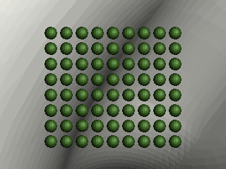
-
 Lasso - Click to draw a closed loop on a part surface. Set the Spacing for anchor points and strong anchor points, then create a lasso loop on the part surface. The loop will automatically close upon releasing the mouse button.
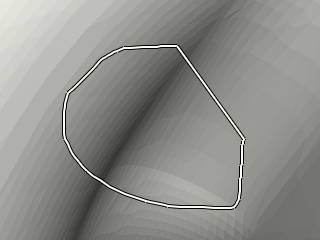
-
- To edit a region of the part, select Region:
-
Under the Tools attributes, Crease, Brush, Box, and Lasso allow for different ways to select editing regions.
With Compute Regions selected, defined regions are shown in green. Edited regions and faces are shown in red.
-
Compute Regions
 allows the detection of down-facing regions and the visualization of "Unsupported" regions of the part. This can be used for the following two purposes:
-
For evaluation of automatically-generated anchor points
-
For evaluation of manually edited anchor points
-
-
Include
 allows selected region areas to be modified.
 -
Exclude
 allows the removal of previous edits.
Use the following shortcut keys to quickly add or clear region selections.-
A - Select all regions as unsupported regions
-
C - Clear all the selections
-
R - Reverse the selections
-
-
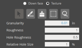
Down face allows the detection of down-facing surface.
-
Texture immediately calculates regions based on texture detection.
-
-
Clicking the Texture radio button immediately calculates regions based on texture detection.
-
Adjust Granularity, Roughness, Hole Roughness, and Relative Hole Size to control texture detection. Press Enter key to apply new detection settings.
-
Regions can be manually edited per typical workflow with Crease, Brush, Box and Lasso commands.
-
Granularity - Used to prevent detection of small regions. Helpful to prevent regioning of small mesh deformities that are often artifacts from texturing process when the mesh was designed. The ratio is defined as a percentage of total triangles found by texture detection. For instance, in a scenario where Granularity Ratio = 1%, if texture detection identifies 500,000 triangles as textured, an area must exceed 5,000 to be considered texture region instead of simple noise.
-
Roughness - Determines the primary boundary of texture regions by defining threshold for roughness. A default value for roughness is computed by analyzing the mesh / implied nominal surface. Roughness is a unitless value similar to surface displacement.
Larger values result in shrinkage of the region boundary because higher roughness is required for detection.
Smaller values result in expansion of the region boundary because lower roughness is required for detection.
-
Hole Roughness - When texture regions are defined, some areas within them may not be part of the detected region. These are considered holes. Larger values result in more holes within the primary region boundary. If Hole Roughness exceeds Roughness, no effect.
-
Relative Hole Size - Determines the hole size value of the region.
-
Smaller values result in less holes within the primary region boundary. Use the value of-1 to disable, using only roughness to evaluate the region.
-
Larger values result in less small texture regions being generated.
-
Smaller values result in more small texture regions being generated.
-
-
- Red regions will not be used when generating supports.
- Click Create to generate supports, or if supports exist, select Support and click Update to update the supports with the changes.
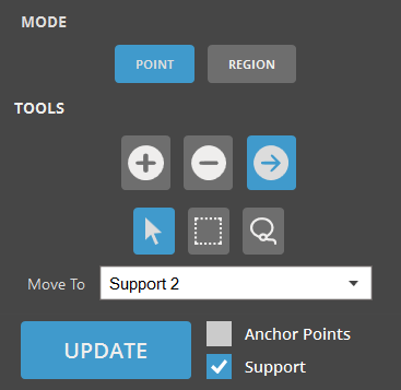
Allows to create and add multiple support regions to a part on the print platform.
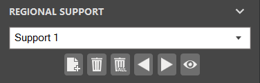
- To add another Support, click Add
 .
. - To delete a Support, select the desired support from the menu using the Navigation Arrows
 and click Delete
  .
. - To delete all supports, click Delete All
 .
. - To view all Supports, click View All
 . The selected Regional Supports are shown in green.
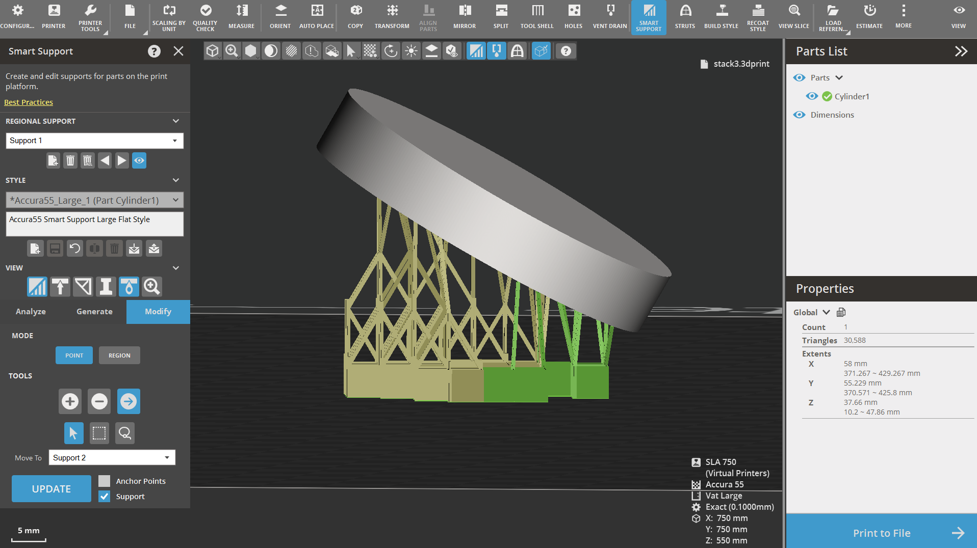
- To move points from one Regional Support to another, select the Move icon
 .
. - Using the Move To dropdown menu, select the desired Support layer.
- Use the Point, Box, or Lasso tool to select the desired points to move.
- Click Update to update the supports with the changes.
Import and export parameters
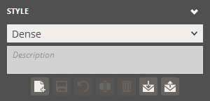
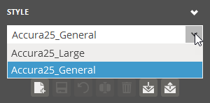
Use the Style options to load and save your own custom styles. The styles are usually aimed at a particular class of models when they are best-utilized. The preset styles are offered with different stated goals.
![]()
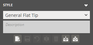
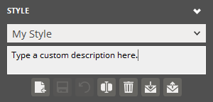
Choose a preset style from the list and refer to its description, or click Add ![]() to create a custom style by duplicating a selected preset. When creating a new style, you can also type a custom description and save it with the style.
to create a custom style by duplicating a selected preset. When creating a new style, you can also type a custom description and save it with the style.
 |
 |
|
Choosing a preset style from the Style list |
Creating a custom style |
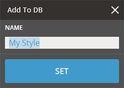
Create a preset:
-
To create a new preset, modify the support parameters as required and click Add
. -
Create a name for the preset and click Set.
-
The preset should now be available from the Style Preset drop-down.
Update a preset:
-
To update a new preset, select the support parameters from the Style Preset drop-down.
-
Update the parameters for the support preset.
-
Click Update
 to save the changes or Restore
  to reset the preset to its initial value.
Rename a preset:
-
To rename a preset, select the preset from the drop-down and click Rename
 .
. -
Change the name for the preset and click Set.
-
The updated preset should now be available from the Style Preset drop-down.
Delete a preset:
To delete a preset, select the preset from the Style Preset drop-down and click Delete ![]() .
.
Import a preset:
-
To import support presets click Import
 below the Style Preset drop-down.
 -
Navigate to the parameter file and click Open.
-
Select the name for the preset and click Set.
Export a preset:
-
To export a preset, select the preset from the Style Preset drop-down.
-
Click Export
 below the Style Preset drop-down.
 -
Navigate to where you want to save the file, give it a name and click Save.
-
This will create a .styleddd file with your selected presets.
See Also