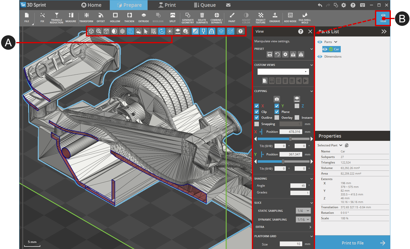
Manipulate the view with the View Overlay and the View panel. Use Clipping to see a section or inside a part.
Note: Features labeled with require a 3D Sprint Pro Subscription for access. With the Basic or Pro Subscription model, you can add specific licensed features labeled with as required. For assistance, please reach out to our technical support team at http://www.3dsystems.com/support or contact your regional sales manager.
Note: Use Alt + Right Click + Drag to rotate the view around the Z-axis of screen view.
Zoom
Zoom in or out, or fit the screen to the platform.
In - Zoom in.
Out - Zoom out.
Extents - Zoom out or in to view parts.
Platform - Zoom out or in to view the Print Platform.
Area - Drag out a rectangle on the screen to zoom in.
Shading
Change the appearance of parts.
Basic - Choose to view objects with Normal shading.
Sharp Edge - Choose to emphasize objects with sharp edges.
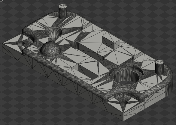
Edge - Choose to view objects with mesh edges.
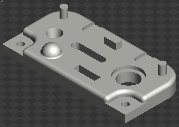
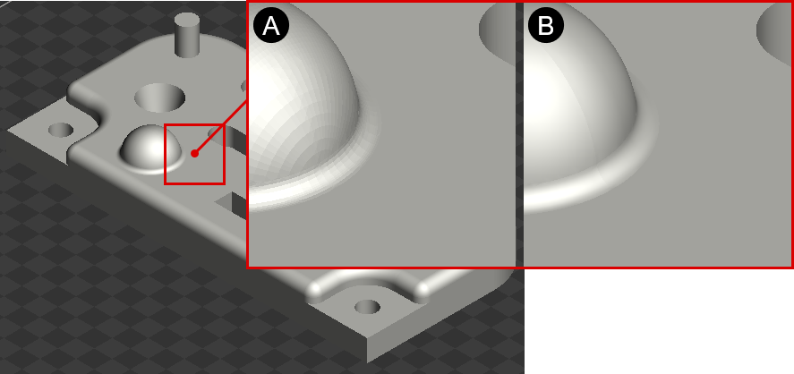
Smooth - Click to switch between rendering options - Smooth shading and Flat shading. When the Smooth shading option is toggled on, adjacent faces within a 30-degree crease angle will be smooth shaded. This tool provides a more realistic representation of objects within the application by minimizing the visibility of unnecessary tessellation.
Transparent - Click to switch between transparent options - Transparent shading and Normal shading.
Basic
Basic transparent
Flat Shading (A) vs. Smooth Shading (B)
Sharp Edge
Sharp Edge transparent
Edge
Edge transparent
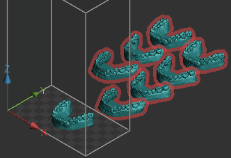
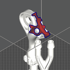
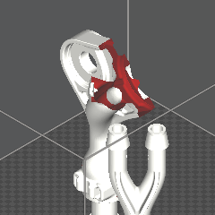
Silhouette for Problem Parts
Show/Hide Silhouette for Problem Parts -See the silhouette of problem parts. Toggle to view the silhouette of problem parts. Use the P shortcut key to view the silhouette of problem parts at any time you need.
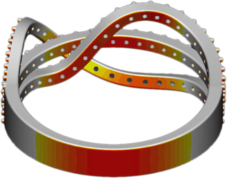
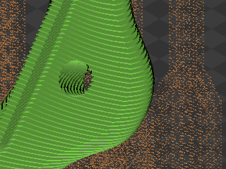
Down Face
Show/Hide Down Face - See overhangs and features that need support. Use the D shortcut key to toggle the visibility of down face on or off. Use the D + R shortcut keys to reset the threshold angle and number of grades for the visibility of down face.
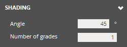
To change the threshold angle and number of grades for down face display, use the options in the View Panel.
Angle - Threshold angle for down face display.
Number of grades - Number of grades or colors to display, ranging from yellow to red.
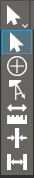
Quick Measure
Quick Measure tools allow for fast measurements in various applications, supporting both parts and auxiliary structures like smart supports and struts.
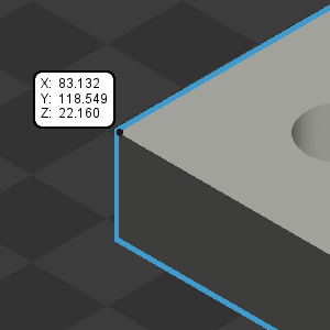
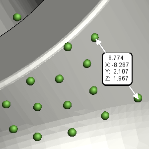
Coordinate - Check the coordinates of a specific point by hovering your mouse cursor over it.
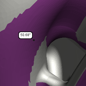
Down Face Angle - Check the down face angle of a selected face with reference to the Printer Platform by hovering your mouse cursor over it.
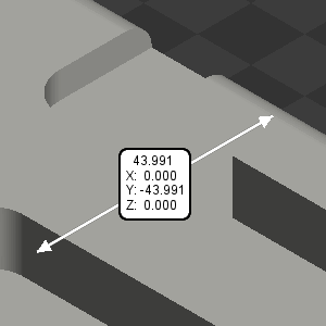
Distance - Measure the distance between two points by selecting them during various commands. For example, measure distances between anchor points or support beams in Smart Supports to determine printability. You can also measure distances on a part to determine if supports are needed when using the Smart Support command.
Thickness - Measure the thickness of a feature by selecting any point on its face. The opposite face will be automatically identified, and the thickness will be measured.
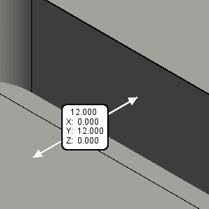
Gap Clearance - Measure the gap between two opposing faces. Select a point on one face, and the opposite face will be automatically detected for measuring the gap.
View Mode
Texture, color and material view mode.
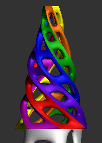
Part Color - Shows both the vertex color and texture mapped color.
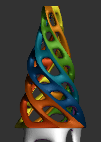
Random Color - Shows parts with different colors.
Material - Show material of the parts.
Hardness - Shows hardness of the parts. This is available when dual materials are applied to ProJet MJP 55XX or ProJet MJP 56XX printers.
Infill - Shows the infill shells of a parts.
Dynamic Rotation Center - Toggle the dynamic rotation center on or off. If this option is toggled on, the center of rotation becomes the location where you right-clicked. If this option is toggled off, the center of rotation is the center of the Print Platform.
Bright Light Theme - Shows parts with a brighter light theme for a better and more accurate display when working with colors. Use the B shortcut key to toggle the visibility of down face on or off.
Orient to Face - Orients a view normal to a selected face. Click Orient to Face and select a face on a model, that you wanted to be parallel to the screen.
Show Selected Part Only - Shows selected parts only and makes all other parts temporarily invisible.
Print Colors - Allows to view parts with colors to be printed.
Print Color - Off
Print Color - On
Material
Show/Hide Material - Toggle to display or hide different material options in the Print tab. Hovering over a material highlights the parts or subparts assigned to it.
Note: When random color is enabled, the material icon is automatically hidden to streamline visibility settings.
Auxiliary Parts
Support - Toggle to view supports in a part.
Struts - Toggle to view created struts in a part.
Vent Drain - Toggle to view vents or drains in a part.
Scale & Offset
Show Scaled Parts - Toggle to view scaled parts.
Select Through
Select Through - Allows to select faces through a model.
View Panel
Preset
Save parameter changes as defaults for later use and restore them at any time you need.
Set Defaults - Click to set parameter changes as defaults for later use.
Restore Defaults - Click to restore any changes to the saved defaults.
Restore Factory Defaults - Restores any changes to the factory defaults.
Import Saved Parameters - Click to import saved parameters.
Export Parameters - Click to export changed parameters for later use.
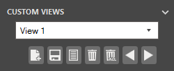
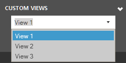
Custom View
Define custom views and reuse them at any time you need.
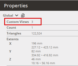
Add - Click to add a new custom view with specified settings. The added custom views are listed in the Custom View List.
Note: The total number of custom views can be found in the Properties panel.
Save - Click to save setting changes to the current custom view.
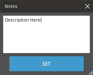
Notes - Click to add descriptions to saved custom views, detailing the significance of each view. This feature is especially useful when sharing views with colleagues.
Delete - Click to delete the current custom view.
Delete All - Click to delete all the saved custom views.
Previous - Click to navigate the previous custom view.
Next - Click to navigate the next custom view.
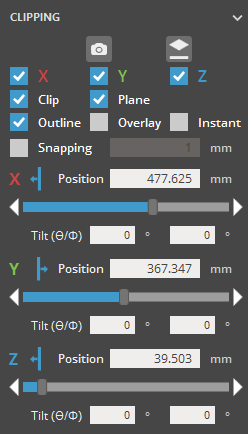
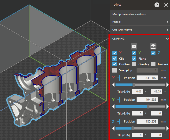
Clipping
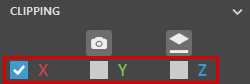
View a section of the part, clip in X, Y and Z direction.
Axis - Select the clipping direction or disable clipping by choosing None. To set the current view direction as the clipping direction, click Camera. To align clipping plane with a selected face, click Face and select a point on the part's surface.
Note: Clipping views support multiple section planes along each axis. Choose clip directions as needed.
Clip - Toggle clipping visibility on or off.
Clip On
Clip Off
Plane - Toggle the visibility of the clipping plane.
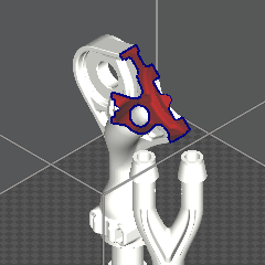
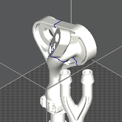
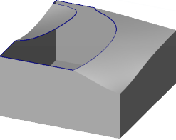
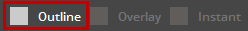
Outline - Toggle the visibility of the clipped section’s outline.
Outline On
Outline Off
Overlay - Enable or disable see-through mode for a transparent view of the clipped section’s outline, providing a clearer outline view. This option is available when Outline is enabled.
Interactive - Toggle visibility of the clipped section's outline while adjusting clipping position. This option is available when Outline is enabled.
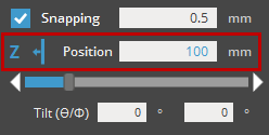
Snapping - Specify the snapping distance. The clipping plane will snap to the entered distance.
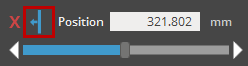
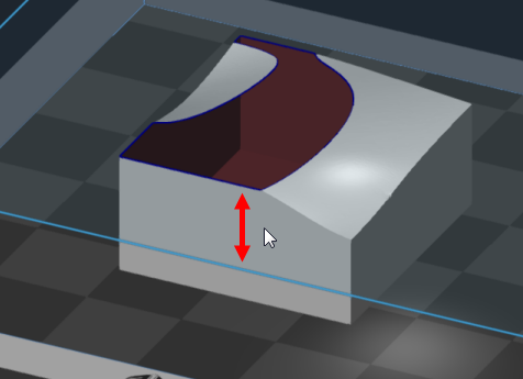
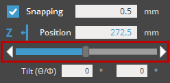
Position - Enter the position of the clipping plane or adjust it with the Position slider. Use the Flip button to reverse the clipping direction.
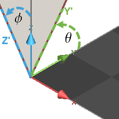
Tilt - Specify tilt angles for the clipping plane relative to the other two axes, based on the normal direction of the clipping plane. for a clipping plane with the X-axis as the normal, tilt angle 1 () rotates around Z-axis and tilt angle 2 () rotates around Y-axis.
To enable clipping, select a clipping axis.
Note: To set the current view direction as the clipping direction, click Camera. To align clipping plane with a selected face, click Face and select a point on the part's surface.
To use Snapping, enable the option and enter a snapping distance.
To adjust the clipping plane position, choose one of the following methods:
Drag the clipping plane with the mouse.
Enter an exact position in the Position text field .
Use the Position slider to adjust the plane position. The slider range is based on the Print Platform's working volume.
To hide the clipping plane, clear the Plane option.
To hide the outline of the clipped section, clear Outline option.
To disable clipping, select None in the Axis options.
Slice
Use the Slice to view a sampled slices from an imported slice file.
The following file types can also have the View Slice command visible.
SLA Printers:
BFF
SLI
The following file types can also have the View Slice command visible.
MJP Printers:
SLC
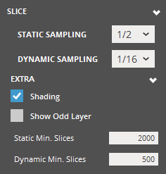
Slice
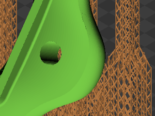
Static Sampling - set the display sampling threshold in a static view. (1/1 - full display; above threshold - sampled display according to specified percentage)
Dynamic Sampling - set the display sampling threshold in a dynamic view. (1/1 - full display during rotation; above threshold - sampled display according to specified percentage during rotation)
1/1 (full display)
1/16 (sampled display)
Extra - Use to view a part with the extra options.
Shading - Toggle to shade a part.
Show Odd Layer - Toggle to view odd layer from a part. This is available when the sampling threshold is above 1/1.
Static Min. Slices - specify the minimum slices displayed in a static view.
Dynamic Min. Slices - specify the minimum slices displayed in a dynamic view.
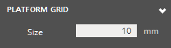
Platform Grid Size
Set the size of the grid overlaid on the Print Platform.
 Smooth