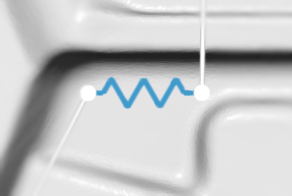
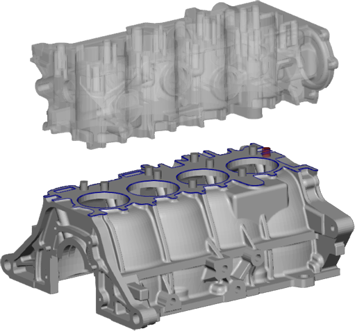
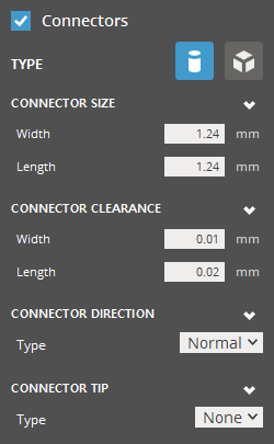
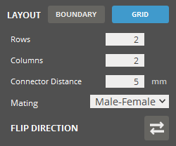
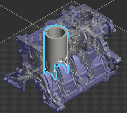
Split

Split a part, to print it in separate parts or to cut away a section of the part. Printing a part in separate parts is useful for printing parts larger than the print volume of the printer, or complex shapes that can only be printed in separate parts. A part can also be split to assign different materials or colors to the split parts. Two methods are available:

Note: (NextDent 5100 Printer) Click Simple UI to switch between the simple and the advanced User Interface. In the Simple UI, only the tools for minimum workflow are visible.


Plane Cut

Cut a part by defining a cutting plane and adding connectors. Connectors are useful for a more stable assembly after printing.

  1. Open a part.

    Get the part from the File > Import command.

  2. In the command bar, click Split.

  3. Choose Plane.

  4. Click on a specific plane XY, YZ or ZX.

  5. Type a value in the Clearance For Parts to set the clearance for cutting parts.

    This removes a section behind the plane equal to the set value.

  6. The cutting plane will be previewed.

  7. Type values for positioning or rotating the cutting plane, or directly manipulate the cutting plane:

    Make sure the plane only covers the part that should be split.

    Note: the Position is relative to the position defined from the following standard.

  8. Click Next.

  9. The split part will be previewed.  

  10. Select Connectors if connectors need to be added.

    Connectors

    Type - Select Cylinder or Cube connectors.

    Connector Width (Min. 0mm) - width of the connector.

    Connector Length (Min. 0mm) - length of the connectors.
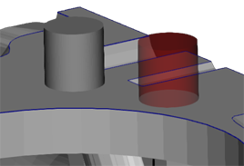
    Connector Clearance

    Clearance Width (Min. 0mm) - width of the clearance between the connector and the part.

    Clearance Length (Min. 0mm) - length of the clearance between the connector and the part.
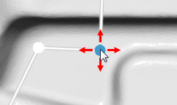
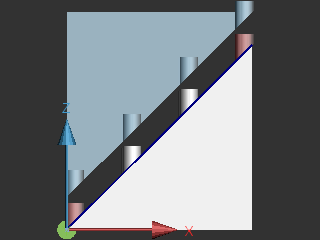
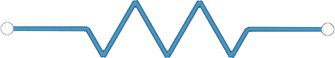
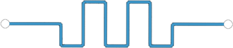
    Connector Direction

    Type - Direction of the connector. Normal direction is perpendicular to a cutting plane. Primary Axis or Plane is selectable as the direction of the connector.

    Normal

    Primary Axis

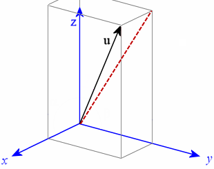
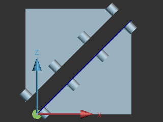
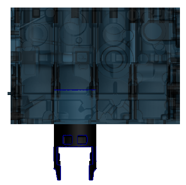
    Note: The largest component of the normal of the cutting plane is the primary axis. The largest 2 components of the normal of the cutting plane is the primary plane. (For example, if the normal of the cutting plane is "u" in the image below, the primary axis is Z axis, the primary plane is the YZ plane; the U vector is projected to the YZ plane. (See the red-dotted line)
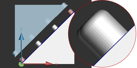
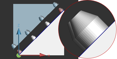
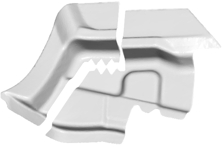
    Connector Tip

    Type - Tip type of the connector. Sphere or Chamber is selectable as the type of the connector. Specify the with or length of the connector.

    Sphere

    Chamfer

    Male Only - select to define the tip of the connect on the Male part only.

  11. Select Boundary or Grid connectors.

    Boundary

    Boundary - Automatically place connectors around the boundary of the cut.

    Number of connectors (Min. 1) - set number of connectors.

    Inset (Min. 0mm) - Distance between connectors and boundary.

    Spacing (Min. 0mm) - space between connectors.

    Mating - define the mating type; Male-Female or Female-Female.

    Male-Female

    Female-Female

    Flip Direction - flip connector direction.

    Grid

    Grid - Place connectors in a grid.

    Rows (Min. 1) - Number of connector rows.

    Columns (Min. 1) - number of connector columns.

    Connector Distance (Min. 0mm) - distance between connectors.

    Mating - define the mating type; Male-Female or Female-Female.

    Flip Direction - flip connector direction.

  12. If a connector is red, it is not possible to place a connector at that position and it will be ignored.

  13. Preview the Split Translation. Translate the previewing part by adjusting the Translate Split Part - Preview slider and make sure the cutting parts are correct.

  14. Click Done.

  15. The part will be split and assembled.

  16. Transform the parts to separate them and to print separately.


Cylinder Cut

Cut a part by defining a cutting cylinder.

  1. Open a part.

    Get the part from the File > Import command.

  2. In the command bar, click Split.

  3. Choose Cylinder.

  4. In the Size option group, type values and press the Enter key on your keyboard to specify Diameter, Upper Depth, and Lower Depth (From a working plane).

  5. Click on a specific plane XY, YZ or ZX.

  6. Type a value in the Clearance For Parts to set the clearance for cutting parts.

    This removes an area inside the cylinder equal to the set value.

  7. The cutting cylinder on the working plane will be previewed.

  8. Type values for positioning or rotating the cutting plane, or directly manipulate the working plane:

    Note: the Position is relative to the position defined from the following standard.

  9. Click Next.

  10. The split part will be previewed.  

  11. Preview the Split Translation. Translate the previewing part by adjusting the Translate Split Part - Preview slider and make sure the cutting parts are correct.

  12. Click Done.

  13. The part will be split.


Line Cut

Cut a part by defining a line and adding teeth. It is useful when a irregular cut is needed.


Add teeth for a more stable assembly. There are three types of teeth:

Triangle

Square

Jigsaw

  1. Open a part.

    Get the part from the File > Import command.

  2. To get a completely straight cut through the part, in the View Overlay and select a View (top, bottom, left or right.)

  3. Open the Split command.

  4. Choose Line.

  5. To start drawing a line, make sure that Add a Point is selected.

  6. To draw the line through the part, click to add points. A line will be created between the points. Double-click to complete the drawing.

    Note: Make sure the line is extended outside the part's boundary.

  7. To remove a single line, select the line by clicking on it and click Remove , or press the Delete key on your keyboard.

  8. To clear all points click Delete

  9. Modify the lines by using the Selector mode and dragging the points.

  10. To add teeth, select a line and click on a tooth type. Triangle, Square, or Jigsaw.

  11. Modify the teeth by dragging the Teeth Placement or the scale slider, clicking Flip to reverse the teeth, or changing the Number of Teeth and the Teeth clearance.

  12. Set the Clearance for Parts. This will create a clearance between the separated parts, for example to make room for glue or printing error.

    Note: The clearance will cut into the part reducing its size.

  13. Click Next.

  14. Preview the Split Translation. Translate the previewing part by adjusting the Translate Split Part - Preview slider and make sure the cutting parts are correct.

  15. To confirm the cut, click Done.

  16. The part will be split. Transform the parts to separate them.


    Note: To save the split parts in separate files, use the Export command.