Supported Printers:
NextDent 5100
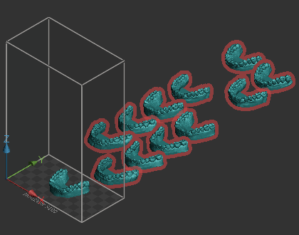
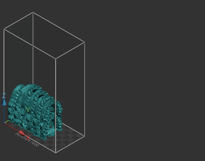
Create arches by stacking multiple hollowed or scaffold parts.
Note: This is available only for NextDent 5100 with Model 2.0 material.
Stacking Arches
Make sure that the NextDent Model 2.0 material is selected.
In the Build Style, make sure that the Ortho Stacked is selected as build style.
In the Print tab, click Stack Arches.
Note: Check the current build style of parts if the minimum support height is 0. Otherwise, an error message box will open when this command runs.
Check if all the parts loaded on the Printer module are selected.
Note: When the dialog opens, all the parts loaded on the Print module will automatically be selected. You can add or remove target parts to or from the selection.
Specify values in the options.
Note: Click Restore  to restore the factory defaults for all settings.
Click Apply.
Check the results.
Note: If there are too many parts and not all arches could be stacked, the warning appears and the extra models are placed outside of the build volume and marked in red in the parts list.
Options
Prepare
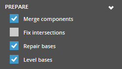
Merge Components - Select to merge components of input arches, which can be called as subparts. The components may be individual teeth, or text with serial numbers.
Fix Intersections - Select to fix intersections that may cause bad mesh topology or failures to process an arch.
Repair Bases - Select to repair bases so that they are fully flat. This is also used to undo shelling/hollowing that may have been done in the Dental CAD package.
Level Bases - Select to remove engravings, such as serial numbers or QR codes, from the base.
Stacking
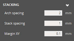
Arch Spacing (Min. 1mm - Max. 10mm; Default is 2mm) - The smallest distance that will be allowed between arches.
Stack Spacing (Min. 1mm - Max. 10mm; Default is 1mm) - The smallest distance that will be allowed between stacks.
Margin XY (Min. 0.05mm - Max. 2mm; Default is 0.1mm) - Controls the X and Y margins between stacks and the perimeter of the platform.
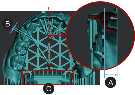
Anterior Supports
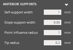
Self-Support Width (Min. 1mm - Max. 10mm; Default is 1mm) - The width where a layer can be self-supported by multiple layers printed beneath. A smaller value can cause more anchor points to be generated, and a larger value can cause less anchor points to be generated.
Slope Support With (Min. 0.05mm - Max. 2mm; Default is 0.05mm) - The radius of range where the lower layer can support upper layer. A smaller value can cause more anchor points to be generated, and a larger value can cause less anchor points to be generated.
Point Influence Radius (Min. 1mm - Max. 6mm; Default is 3mm) - The radius a single inner anchor point can support in the same layer, but does not address point density along boundary or corner case. A smaller value will result in a higher density of inner anchor points and a larger value will result in a sparser density of inner anchor points.
Tip Radius (Min. 0.15mm - Max. 0.25mm; Default is 0.2mm) - The radius of tips that touch the part surface.
Pillar Supports
The pillars are between the platform and the lowest arch, but also between arches.
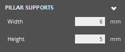
Width (Min. 5mm - Max. 7mm; Default is 6mm) - The width of pillars, that support the posterior regions of each quadrant.
Height (Min. 4mm - Max. 6mm; Default is 5mm) - The height of pillars, that support the posterior regions of each quadrant.
Hollowing
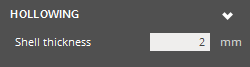
Shell Thickness (Min. 1.5mm - Max. 3mm; Default is 2mm) - The thickness of a resulting shell.
Scaffolding
Scaffolding is the hex pattern that gets created within the base of an arch.
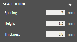
Spacing (Min. 5mm - Max. 10mm; Default is 7mm) - The distance between parallel scaffolding beams.
Height (Min. 1.5mm - Max. 2.5mm; Default is 2.5mm) - The height of scaffolding beams, that are measured from the base.
Thickness (Min. 0.5mm - Max. 1mm; Default is 0.8mm) - The width of scaffolding beams.
Advanced
In the Advanced option group, lattice supports and base bars can be added to the arches.
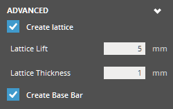
Create lattice - Determines whether to create lattice supports and add them to the part.
Lattice Lift (Min. 0mm - Max. 10mm; Default is 4mm) - Specify the offset distance of the lattice supports from the down face of the part.
Lattice Thickness (Min. 0.75mm - Max. 1.5mm; Default is 1mm) - Specify the thickness of the lattice supports.
Create Base Bar - Determines whether to create a base bar and add it to the part.
|
|
See Also