Supported Printers:
NextDent 5100
Figure 4 Standalone
Figure 4 Modular
Supported Printers:
SLA-Printers
Create custom, high-level support struts to reduce support volume usage, improve the print quality after cleaning parts and supports.
Proceed to one of the following topics for more information:
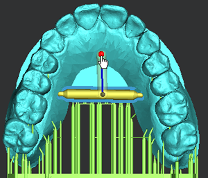
Creating Struts for Dental Applications
This manual process allows you to generate struts as supports and as cross-bracing in place of auto-generated supports. This process can also be used when auto-generated supports are built on your parts.
In the Print tab, click Struts.
Change the options and parameters as you desired.
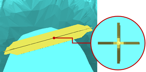
In the Adjust Normal under the Tip, ensure that this option is set to On.
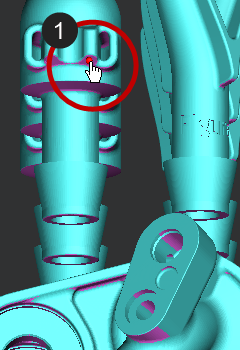
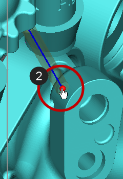
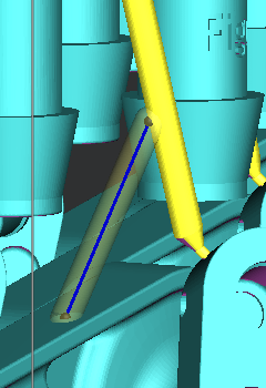
Click two points on a model to create a new strut between them.
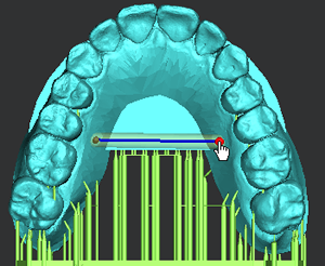
Note: Once two points are defined on a model, the preview of a strut appears. You can edit the previewed strut by clicking and dragging one of end point of the strut or clicking on a new position.
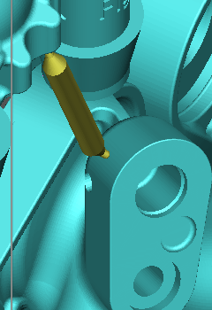
Press the Spacebar or click Apply to create a strut on the model. For more information on the Keyboard shortcuts available in the command, see Keyboard Shortcuts.
Note: You can add a new strut by the following methods:
Clicking two points on a model
Clicking a point on an existing strut and then click a point on a model
Clicking points between two existing struts
Clicking points between an existing support and a model
Use Ctrl + Click to set the start point of a new strut on an existing strut or support, and then click a point on the model.
Press the Spacebar or click Apply to add a new strut.
Note: If necessary, you can delete the created strut by clicking or lasso-dragging and pressing the DEL key.
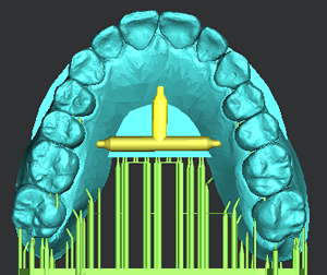
Note: The committed struts are used as auxiliary components of the model, similar to supports.
Toggle on or off the Show/Hide Struts button found at the top corner of the working view to control the visibility of the created struts.
![]()
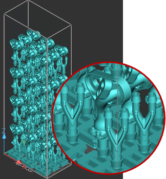
Creating Struts for Industrial Applications
This manual process allows you to generate struts as supports and as cross-bracing in place of auto-generated supports. This process can also be used when auto-generated supports are built on your parts.
The following example assumes that you are using a stack built by an array of parts. For more information on creating a stack, see Create Stack.
In the Print tab, click Struts.
Change the options and parameters as you desired.
In the Adjust Normal under the Tip, ensure that this option is set to On.
Toggle on the Show/Hide Down Faces button found at the top corner of the working view or click D to toggle the Down Faces display on.
![]()
This allows a color visualization of down-facing regions to avoid under-supporting when manually creating supports.
Note: With down-face visualization on, you can create struts to support the down-facing regions and any initial layers of a part.
Click two points on a model to create a new strut between them.
Note: Once two points are defined on a model, the preview of a strut appears. You can edit the previewed strut by clicking and dragging one of end point of the strut or clicking on a new position.
Press the Spacebar or click Apply to create a strut on the model.
Note: You can add a new strut by the following methods:
Clicking two points on a model
Clicking a point on an existing strut and then click a point on a model
Clicking points between two existing struts
Clicking points between an existing support and a model
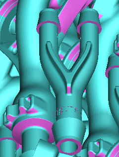
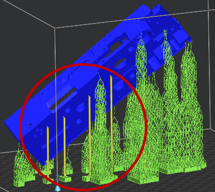
Note: Check that the angles of the struts are self-supporting. To be safe, 40°-90° from the horizontal should be fairly self-supporting; otherwise, add more struts for supporting them.
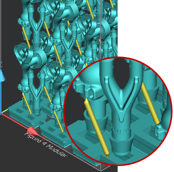
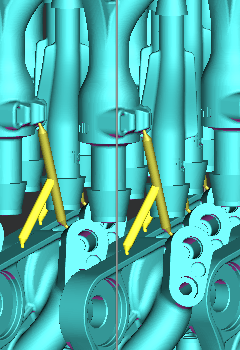
When struts are created, that strut will be replicated across the entire array. The struts will also be replicated between the first row of parts and the base using the initial point on the top part and the trajectory of the strut. The strut will then find the close point on the base on which to connect.
Use Ctrl + Click to set the start point of a new strut on an existing strut or support, and then click a point on the model.
Press the Spacebar or click Apply to add a new strut. For more information on the Keyboard shortcuts available in the command, see Keyboard Shortcuts.
Note: If necessary, you can delete the created struts by clicking or lasso-dragging and pressing the DEL key.
Note: The committed struts are used as auxiliary components of the model, similar to supports.
Toggle on or off the Show/Hide Struts button found at the top corner of the working view to control the visibility of the created struts.
![]()
![]()
Options
Preset
Save parameter changes as defaults for later use and restore them at any time you need.
![]()
![]() Set Defaults
- Click to set parameter changes as defaults for later use.
Set Defaults
- Click to set parameter changes as defaults for later use.
![]() Restore
Defaults - Click to restore any changes to the saved defaults.
Restore
Defaults - Click to restore any changes to the saved defaults.
![]() Restore
Factory Defaults - Restores any changes to the factory defaults.
Restore
Factory Defaults - Restores any changes to the factory defaults.
![]() Import Saved
Parameters - Click to import saved parameters.
Import Saved
Parameters - Click to import saved parameters.
![]() Export Parameters
- Click to export changed parameters for later use.
Export Parameters
- Click to export changed parameters for later use.
Parameters
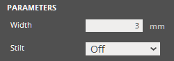
Width (Min. 0.5mm - Max. 15mm) - the width of the main body of a strut.
Note: It is recommended that you refrain from making the width too small and smaller than the Tip Width.
Stilt - Determines whether to create a stilt by one click on a model. A stilt is used as an additional support to minimize chances of build failures.
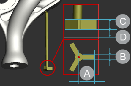
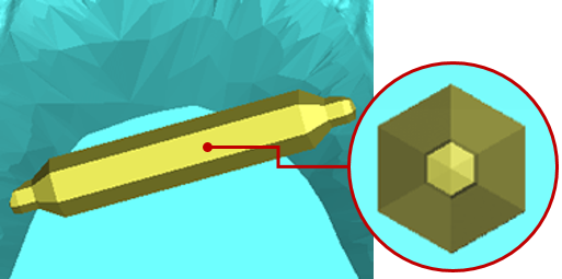
Cross Section
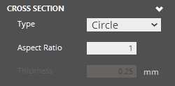
Type - The cross-section type of a strut. There are four types of cross-sections: Circle, Rectangle, Hexagon, and Cross, and Empire. The default is Circle.
Circle
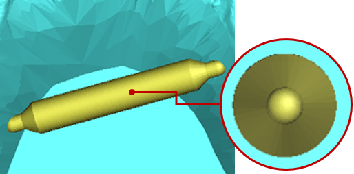
Rectangle
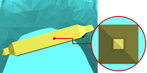
Hexagon
Cross
Empire

Aspect Ratio (Min. 0.2 - Max. 1) - The aspect ratio of the cross section of a strut. This controls the ratio between the x and y of the cross-section. The smaller the ratio, the smaller the x-dimension become relative to the y-dimension or the width.
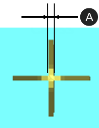
Thickness (Min. 0.005mm - Max. 0.2mm) - Controls the thickness of the Cross type cross-section of a strut.
Note: This is available only for Cross type.
|
|
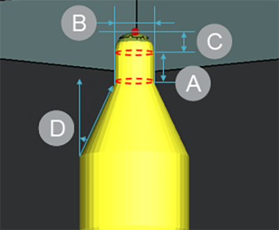
Tip
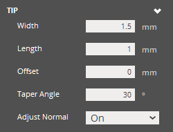
Width (Min. 0.01mm - Max. 3mm) - the width of the tip of a strut.
Length (Min. 0mm - Max. 8mm) - the length of the tip of a strut.
Offset (Min. 0mm - Max. 8mm) - the offset distance from of a picked reference point on a model to the tip of a strut.
Taper Angle (Min. 15° - Max. 90°) - the angle of the taper in a strut.
|
|
Adjust Normal - Adjusts the normal of the cross-section of the tip to the normal of the surface where a reference point is defined. This prevents supports intersecting a surface at an off angle, which would create larger cross-sections and as a result, support scarring than you desired when removing supports.
Stilt
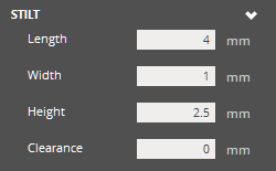
Length (Min. 0.5mm - Max. 10mm) - the length of stilt roots.
Width (Min. 0.05mm - Max. 10mm) - the width of stilt roots.
Height (Min. 0.5mm - Max. 10mm) - the height of stilt roots.
Clearance (Min. 0mm - Max. 20mm) - the offset distance from the Print Platform.
|
|
Taper
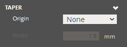
Origin - The origin of the taper in a strut. This controls where the taper originates from on a strut, from the tip width to the strut width.
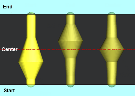
Width (Min. 0.2mm - Max. 15mm) - the width of the taper in a strut.
Operation |
Keyboard Shortcut |
Prevents selection of existing strut points. This also allows to create a new strut on an existing strut. |
Ctrl + Click |
Complete creation (Set Button) |
Spacebar |
Delete selected struts |
Delete / Backspcace |
Clear the selection of struts |
C |
Select all Note: This is useful when you want to modify parameters for all selected struts at a time. |
A |
Select similar struts |
S + Click |
Undo / Redo |
Ctrl + Z / Ctrl + Y |
See Also