Add Part
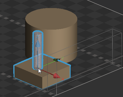
The Add Part command allows for basic assembly in 3D Sprint. Add Part is an alternative way to position and orient “tool” parts onto “target” parts using a mating surface method and relative transforms. To use this command, you will designate a Target Part (fixed) and a Tool Part (moving). Tool Parts can be moved using the Move / Rotate controls. Tool parts can also have their material property set to “air” now, when this is set, part booleans are performed at slice time.
To use this command, follow these steps:
-
Prepare the parts or objects on the Print Platform, and select one or multiple objects to designate as target or tool parts.
-
From the Print Tab, select the Add Part command.
-
Decide which tool parts you want to position on the target parts. Proceed with one of the following processes to determine the tool part.
-
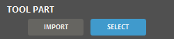
If a suitable tool part is already prepared on the Print Platform, click Select in the Tool Part option to choose the desired tool part.
-
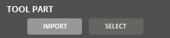
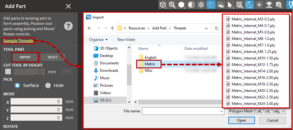
In case there is no appropriate tool part on the Print Platform, click Import to bring in preset tool parts.
Note: You can access the preset tool parts via a convenient “Sample Threads” link within the dialog.
-
-
If you need to cut the tool part, select the Cut Tool by Height check box and specify the height value. Click Cut to trim the tool part to the specified height.

-
Once the tool part is selected and configured as desired, choose the stationary part where you want to position the selected tool part on the target part.
-
Use the available transform commands to precisely position the tool part on the desired location of the target part.
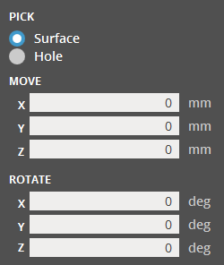
Surface - Allows the placement of tool parts on any selected surface of the target part.
Hole - Snaps the parts to holes created with the Holes command.
Move and Rotate are used to transform the Tool part in relation to the target part. -
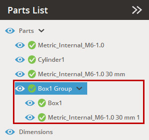
After you've positioned the tool part as needed, click Add Part to add it to the target part. This action will group the tool and target parts in the Parts List.