 Auto Place
Automatically place part files on the Print Platform in an optimal way for the current printer. It is useful for quickly placing multiple parts onto the print area.
Note: Features labeled with ![]() require a 3D Sprint Pro Subscription for access. With the Basic or Pro Subscription model, you can add specific licensed features labeled with
require a 3D Sprint Pro Subscription for access. With the Basic or Pro Subscription model, you can add specific licensed features labeled with ![]() as required. For assistance, please reach out to our technical support team at http://www.3dsystems.com/support or contact your regional sales manager.
as required. For assistance, please reach out to our technical support team at http://www.3dsystems.com/support or contact your regional sales manager.
Note: If placing several large parts, it may not be possible to use the Auto Place command. Manually orient and place the parts using the Transform tool instead.
-
In the Print tab, click Auto Place.
-
Select options.
-
Select the parts to be placed. If there is no selection, all existing parts will be placed automatically on the Print Platform.
-
Click Set.
Options
Auto-Place Presets
![]()
Customized Auto-place parameters can be saved as a preset and loaded in the Auto Place command.
To create a new preset:
-
Enter the values for each parameter.
-
Click New
 .
. -
Enter a name for the Auto-Place preset.
To update a preset:
-
Select a preset from the drop-down.
-
Enter the values for each parameter.
-
Click Update
 .
. -
If necessary, click Rename
 to rename the selected preset and then change to a new name in the Name input box.
To delete a preset:
-
Select a preset from the drop-down.
-
Click Delete
 .
.
To restore preset to the default values:
-
Click Restore
 .
. -
Click OK on the dialog box.
Auto-Place Parameters
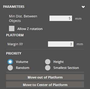
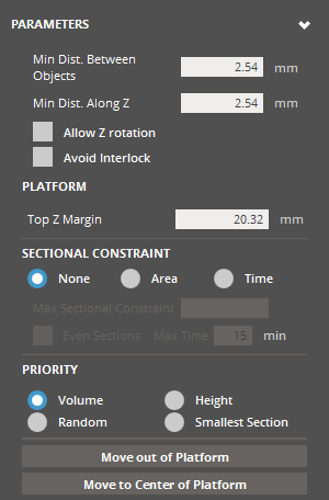
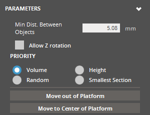
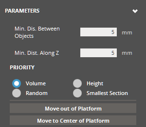
Min. Distance Between Objects (Min. 0mm - Max. 50mm) - The smallest distance that will be allowed between parts. This is set according to the requirements of the current printer.
Min. Dist. Along Z (Min. 0mm - Max. 50mm) - The smallest distance that will be allowed between parts on along the Z axis. This is set according to the requirements of the current printer.
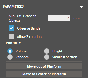
Allow Z-rotation - Allows parts to be rotated in Z.
Platform Margin XY (Min. 0mm - Max. 50mm; Default is 20mm for ProX 950, 10mm for other SLA Printers) - A margin distance from the edge of the Print Platform along the XY axis.
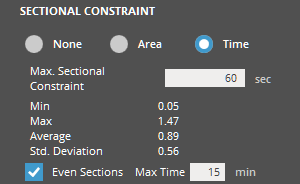
Sectional Constraint - Allows to specify maximum scan time or cross-section area per layer. Select the Area or Time, and enter a limit value in the input box. To evenly distribute parts across the entire Print Platform, select the Even Sections option. After the initial auto-placement, this option enhances the uniformity of cross-sectional area distribution along the Z direction of the build volume. This is applicable only to translations. The even sectioning process is controlled by the maximum time-out defined in the Max Time option.
Priority - Determines what priority criteria is used to arrange the parts: Volume, Height, Random, or Smallest Section
Volume - Parts are auto-placed by largest volume first, descending to smallest volume parts.
Height - Parts are auto-placed by largest Z-extent first, descending to smallest Z-extent parts.
Random - Parts are auto-placed in a random order.
Smallest Section - Parts are auto-placed by smallest XY-section first, descending to largest XY-section parts.
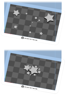
Move out of Platform - Click to move parts outside the Print Platform.
Move to Center of Platform - Click to move parts to the center of the Print Platform.
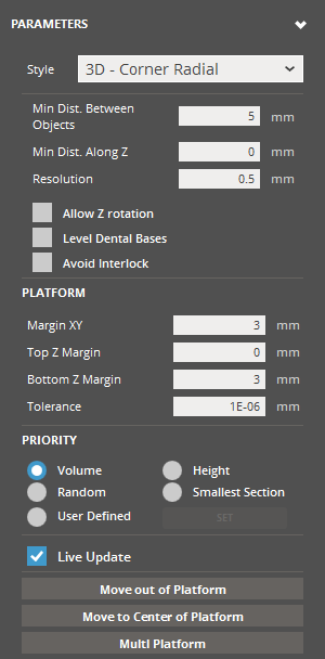
![]() Advanced Auto-Place Parameters
Advanced Auto-Place Parameters
|
|
2D Styles |
3D Styles |
|---|---|---|
|
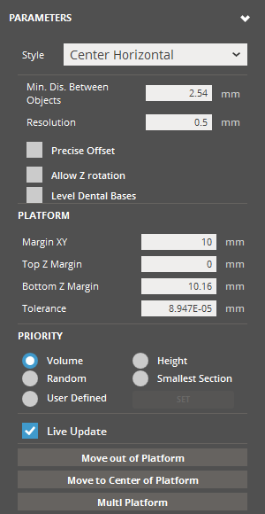
Style |
The designate the placement style defines the overall arrangement strategy of parts. Selecting a style from the below categories will show only pertinent options in the rest of the dialog: |
|
|
|
|
|
|
2D Nesting Styles - Geometry-based 2D strategy. Helpful for technologies, where efficient utilization of the XY footprint is desirable, but parts stacking above each other in Z is not. Parts will auto place within the XY footprint.
2D Placement Styles - Bounding-box based 2D strategy, like the above, but more conservative about part spacing, as bounding boxes will not intersect. |
3D Nesting Styles - Geometry-based 3D strategy. Helpful for technologies, where utilization of the full volume is desirable. Parts will auto place anywhere within the build volume.
3D Placement Styles - Bounding-box based 3D strategy, like the above, but more conservative about part spacing, as bounding boxes will not intersect. |
|
|
Minimum Distance Between Objects |
Specify the smallest allowable distance between parts. |
Specify the smallest allowable distance between parts in XY. |
|
Minimum Distance Along Z |
|
Specify the smallest allowable distance between parts in Z. If not enabled, the result will use the specified value of Min. Dis. Between Object. |
|
Resolution |
Set the resolution/increment of the algorithm translations. |
|
|
Precise Offset |
Enable this option to specify that the Min. Dis. Between Object value is also the desired distance between objects. Results in more compactness of results, but is more computationally expensive. |
|
|
Allow Z Rotation |
Enable this option to allow objects to be rotated about the Z axis. Helpful to enable if you're seeking to optimize volume efficiency. Once this option is enabled it will give access to the following parameters: All Rotation - Generates several versions of rotations for each part, including x, y and z, and all versions are used in the auto-placement according to priority/success. Note: Total number of rotations is fixed, if you turn on the All Rotation option, you get less Z rotations. Rotate from Principal Axis (2D Styles) - Allow rotation from the principal axis. Number Rotations - The number of candidate positions (rotations) within angle specified in the Angle Range option. Angle Range - Specify the angle range that allows optimizing orientation iteratively from the current orientation of the part. |
|
|
|
Enable this option to allow objects to be oriented so that their flat base is parallel to the Printer Platform. Note: This option is available only for the TruShell users. |
|
|
Avoid Interlock |
|
Enable this option to perform interlock checks/avoid interlocks. Interlocking is the case of 3D nesting where objects may inadvertently become bound by each other, becoming inseparable. |
|
Margin XY (Min. 0mm - Max. 50mm) |
Define the platform XY margin inset width. Objects will not be placed within the margin. |
|
|
Top Z Margin (Min. 0mm) |
Define the platform top Z margin inset width. Objects will not be placed within the margin. |
|
|
Bottom Margin Z (Min. values set in the Minimum Z Height of the Build Style) |
Define the platform bottom Z margin inset width. Objects will not be placed within the margin. |
|
|
Tolerance (Min. 0mm - Max. 1mm) |
Define the width of the acceptance band outwards from the platform boundary/margin. A larger value translates to a wider acceptance band, which means that parts may exceed the platform space more. |
|
|
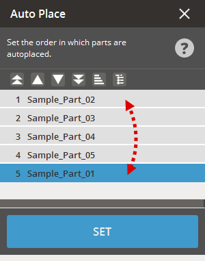
Priority |
Determine the ordering convention for how objects are chosen and then translated for auto place. Volume - Objects are placed by largest volume first, descending to smallest volume parts. Height - Objects are placed by largest Z-extent first, descending to smallest Z-extent parts. Random - Objects are placed in a random order. Smallest Section - Objects are placed by smallest XY-section first, descending to largest XY-section parts. User Defined - The priority of objects can be reordered manually through a simple interface within the command.
To change the listing and auto-placement sequence of parts on the Printer Platform, follow these steps:
|
|
|
Live Update |
Enable in order to see continuous graphics updating as objects are re-positioned. |
|
|
Post Processing |
||
|
Move out of Platform |
Move selected part(s) out of platform bounds. |
|
|
Move to Center of Platform |
Move part(s) to the center of the platform based on the centroid of the part selection bounding box (preserves spatial relationship of selected parts). |
|
|
Multi Platform |
Initializes the algorithm to begin sorting like the "Set" button normally does, with an additional behavior: if the total part quantity exceeds the capacity of the initial platform, extra parts are arranged in space to simulate additional platforms. |
|
![]() Auto-Place Parameters
Auto-Place Parameters
|
|
2D Styles |
3D Styles |
|---|---|---|
|
Style |
The designate the placement style defines the overall arrangement strategy of parts. Selecting a style from the below categories will show only pertinent options in the rest of the dialog: |
|
|
|
|
|
|
2D Nesting Styles - Geometry-based 2D strategy. Helpful for technologies, where efficient utilization of the XY footprint is desirable, but parts stacking above each other in Z is not. Parts will auto place within the XY footprint.
2D Placement Styles - Bounding-box based 2D strategy, like the above, but more conservative about part spacing, as bounding boxes will not intersect. |
3D Nesting Styles - Geometry-based 3D strategy. Helpful for technologies, where utilization of the full volume is desirable. Parts will auto place anywhere within the build volume.
3D Placement Styles - Bounding-box based 3D strategy, like the above, but more conservative about part spacing, as bounding boxes will not intersect. |
|
|
Minimum Distance Between Objects |
Specify the smallest allowable distance between parts. |
Specify the smallest allowable distance between parts in XY. |
|
Minimum Distance Along Z |
|
Specify the smallest allowable distance between parts in Z. If not enabled, the result will use the specified value of Min. Dis. Between Object. |
|
Resolution |
Set the resolution/increment of the algorithm translations. |
|
|
Precise Offset |
Enable this option to specify that the Min. Dis. Between Object value is also the desired distance between objects. Results in more compactness of results, but is more computationally expensive. |
|
|
Allow Z Rotation |
Enable this option to allow objects to be rotated about the Z axis. Helpful to enable if you're seeking to optimize volume efficiency. Once this option is enabled it will give access to the following parameters: All Rotation - Generates several versions of rotations for each part, including x, y and z, and all versions are used in the auto-placement according to priority/success. Note: Total number of rotations is fixed, if you turn on the All Rotation option, you get less Z rotations. Rotate from Principal Axis (2D Styles) - Allow rotation from the principal axis. Number Rotations - The number of candidate positions (rotations) within angle specified in the Angle Range option. Angle Range - Specify the angle range that allows optimizing orientation iteratively from the current orientation of the part. |
|
|
|
Enable this option to allow objects to be oriented so that their flat base is parallel to the Printer Platform. Note: This option is available only for the TruShell users. |
|
|
Avoid Interlock |
|
Enable this option to perform interlock checks/avoid interlocks. Interlocking is the case of 3D nesting where objects may inadvertently become bound by each other, becoming inseparable. |
|
Margin XY (Min. 0mm - Max. 50mm) |
Define the platform XY margin inset width. Objects will not be placed within the margin. |
|
|
Top Z Margin (Min. 0mm) |
Define the platform top Z margin inset width. Objects will not be placed within the margin. |
|
|
Bottom Margin Z (Min. values set in the Minimum Z Height of the Build Style) |
Define the platform bottom Z margin inset width. Objects will not be placed within the margin. |
|
|
Tolerance (Min. 0mm - Max. 1mm) |
Define the width of the acceptance band outwards from the platform boundary/margin. A larger value translates to a wider acceptance band, which means that parts may exceed the platform space more. |
|
|
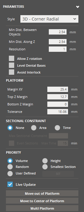
Sectional Constraint |
|
Set optional additional constraints on the result of auto place. None - No additional constraints on the auto place result. Area - Constrain the auto place result by XY cross-sectional area per layer. Enter the maximum range of cross-sectional area in the Max. Sectional Constraint input box to specify the area that should be taken into consideration. To evenly distribute parts across the entire Print Platform, select the Even Sections option. After the initial auto-placement, this option enhances the uniformity of cross-sectional area distribution along the Z direction of the build volume. This is applicable only to translations. The even sectioning process is controlled by the maximum time-out defined in the Max Time option. Time - Constrain the auto place result by estimated time to produce each layer during printing. Sectional Constraint Range - Two numerical input boxes where the lower and upper limit of constraint range can be designated. Not available / applicable when None is selected. |
|
Priority |
Determine the ordering convention for how objects are chosen and then translated for auto place. Volume - Objects are placed by largest volume first, descending to smallest volume parts. Height - Objects are placed by largest Z-extent first, descending to smallest Z-extent parts. Random - Objects are placed in a random order. Smallest Section - Objects are placed by smallest XY-section first, descending to largest XY-section parts. User Defined - The priority of objects can be reordered manually through a simple interface within the command.
To change the listing and auto-placement sequence of parts on the Printer Platform, follow these steps:
|
|
|
Live Update |
Enable in order to see continuous graphics updating as objects are re-positioned. |
|
|
Post Processing |
||
|
Move out of Platform |
Move selected part(s) out of platform bounds. |
|
|
Move to Center of Platform |
Move part(s) to the center of the platform based on the centroid of the part selection bounding box (preserves spatial relationship of selected parts). |
|
|
Multi Platform |
Initializes the algorithm to begin sorting like the "Set" button normally does, with an additional behavior: if the total part quantity exceeds the capacity of the initial platform, extra parts are arranged in space to simulate additional platforms. |
|
![]() Auto-Place Parameters
Auto-Place Parameters
|
|
2D Styles |
3D Styles |
|---|---|---|
|
Style |
The designate the placement style defines the overall arrangement strategy of parts. Selecting a style from the below categories will show only pertinent options in the rest of the dialog: |
|
|
|
|
|
|
2D Nesting Styles - Geometry-based 2D strategy. Helpful for technologies, where efficient utilization of the XY footprint is desirable, but parts stacking above each other in Z is not. Parts will auto place within the XY footprint.
2D Placement Styles - Bounding-box based 2D strategy, like the above, but more conservative about part spacing, as bounding boxes will not intersect. |
3D Nesting Styles - Geometry-based 3D strategy. Helpful for technologies, where utilization of the full volume is desirable. Parts will auto place anywhere within the build volume.
3D Placement Styles - Bounding-box based 3D strategy, like the above, but more conservative about part spacing, as bounding boxes will not intersect. |
|
|
Minimum Distance Between Objects |
Specify the smallest allowable distance between parts. |
Specify the smallest allowable distance between parts in XY. |
|
Minimum Distance Along Z |
|
Specify the smallest allowable distance between parts in Z. If not enabled, the result will use the specified value of Min. Dis. Between Object. |
|
Resolution |
Set the resolution/increment of the algorithm translations. |
|
|
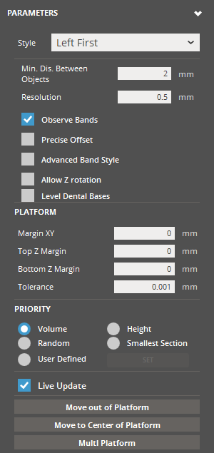
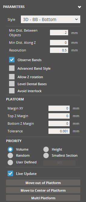
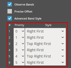
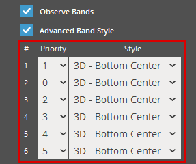
Observe Bands |
Observes the current bands and places the models in single band by priority. |
|
|
Precise Offset |
Enable this option to specify that the Min. Dis. Between Object value is also the desired distance between objects. Results in more compactness of results, but is more computationally expensive. |
|
|
Advanced Band Style |
Refine the placement strategy of parts in detail by specifying a distinct 2D placement style according to priority within the current band.
Note: This option becomes available when the Observe Bands option is selected. Note: The Auto Lane Alternation will be overwritten by Advance Band Style when toggled on. |
Refine the placement strategy of parts in detail by specifying a distinct 3D placement style according to priority within the current band.
Note: This option becomes available when the Observe Bands option is selected. Note: The Auto Lane Alternation will be overwritten by Advance Band Style when toggled on. |
|
Allow Z Rotation |
Enable this option to allow objects to be rotated about the Z axis. Helpful to enable if you're seeking to optimize volume efficiency. Once this option is enabled it will give access to the following parameters: All Rotation - Generates several versions of rotations for each part, including x, y and z, and all versions are used in the auto-placement according to priority/success. Note: Total number of rotations is fixed, if you turn on the All Rotation option, you get less Z rotations. Rotate from Principal Axis (2D Styles) - Allow rotation from the principal axis. Number Rotations - The number of candidate positions (rotations) within angle specified in the Angle Range option. Angle Range - Specify the angle range that allows optimizing orientation iteratively from the current orientation of the part. |
|
|
|
Enable this option to allow objects to be oriented so that their flat base is parallel to the Printer Platform. Note: This option is available only for the TruShell users. |
|
|
Avoid Interlock |
|
Enable this option to perform interlock checks/avoid interlocks. Interlocking is the case of 3D nesting where objects may inadvertently become bound by each other, becoming inseparable. |
|
Margin XY (Min. 0mm - Max. 50mm) |
Define the platform XY margin inset width. Objects will not be placed within the margin. |
|
|
Top Z Margin (Min. 0mm) |
Define the platform top Z margin inset width. Objects will not be placed within the margin. |
|
|
Bottom Margin Z (Min. values set in the Minimum Z Height of the Build Style) |
Define the platform bottom Z margin inset width. Objects will not be placed within the margin. |
|
|
Tolerance (Min. 0mm - Max. 1mm) |
Define the width of the acceptance band outwards from the platform boundary/margin. A larger value translates to a wider acceptance band, which means that parts may exceed the platform space more. |
|
|
Priority |
Determine the ordering convention for how objects are chosen and then translated for auto place. Volume - Objects are placed by largest volume first, descending to smallest volume parts. Height - Objects are placed by largest Z-extent first, descending to smallest Z-extent parts. Random - Objects are placed in a random order. Smallest Section - Objects are placed by smallest XY-section first, descending to largest XY-section parts. User Defined - The priority of objects can be reordered manually through a simple interface within the command.
To change the listing and auto-placement sequence of parts on the Printer Platform, follow these steps:
|
|
|
Live Update |
Enable in order to see continuous graphics updating as objects are re-positioned. |
|
|
Post Processing |
||
|
Move out of Platform |
Move selected part(s) out of platform bounds. |
|
|
Move to Center of Platform |
Move part(s) to the center of the platform based on the centroid of the part selection bounding box (preserves spatial relationship of selected parts). |
|
|
Multi Platform |
Initializes the algorithm to begin sorting like the "Set" button normally does, with an additional behavior: if the total part quantity exceeds the capacity of the initial platform, extra parts are arranged in space to simulate additional platforms. |
|
See Also