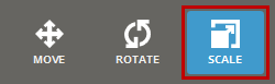
Move, Rotate or scale parts. Either use the mouse or enter transformation values in the command panel to transform parts.
Note: First use the Grouping command to separate subparts so as to transform them as a whole rather.
Note: Features labeled with require a 3D Sprint Pro Subscription for access. For assistance, please reach out to our technical support team at http://www.3dsystems.com/support or contact your regional sales manager.
In the Prepare or Print tab, click Transform.
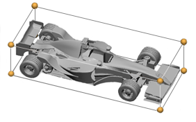
Select the parts to be transformed. A bounding box will appear around the parts.
Note: Click Simple UI to switch between the simple and the advanced User Interface. In the Simple UI, only the tools for minimum workflow are visible.
Transform Panel
In the Transform command, each option allows changes to be made using mouse commands or by entering absolute or incremental values for move, rotation, or scale in the Transform dialog.
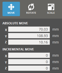
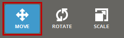
Move
Absolute Move - Allows to adjust the position of a selected object based on the platform origin.
Incremental Move - Allows to change the position of a selected object relative to its current location. Enter a value and pressing Enter to apply the change.
Note: Incremental adjustments affect the object along a single axis at a time. If you enter multiple values, only the last value will be applied to the transformation.
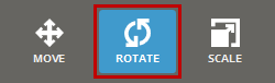
Rotate
Relative Rotate - Allows to adjust to the rotation of a selected object based on its orientation from the initial state of the command.
Incremental Rotate - Allow to change the rotation of a selected object relative to its current orientation. Enter a value and pressing Enter to apply the change.
Note: Incremental adjustments affect the object around a single axis at a time. If you enter multiple values, only the last value will be applied to the transformation.
Scale
Uniform Scaling -Resizes a selected object by the same scale factor across all axes, ensuring the object's proportions and geometry remain consistent. By entering a specific value in either the Absolute Scale or Incremental Scale options with Uniform Scaling enabled, the object's size will increase or decrease uniformly along all axes.
Note: This option is useful for resizing objects while maintaining their original shape and aspect ratio.
Absolute Scale - Allows to adjust to the scale of a selected object based on its size from the initial state of the command.
Incremental Scale - Allow to change the scale of a selected object relative to its current size. Enter a value and pressing Enter to apply the change.
Note: Incremental adjustments affect the object along a single axis at a time. If you enter multiple values, only the last value will be applied to the transformation.
About Incremental and Absolute transformation.
Absolute transformations allows for changes based on the initial scale and rotation of part or position relative to the platform origin. Incremental transformation allows for changes relative to the current state of the part.
For example, a part at position (0, 0, 0) on the platform has an incremental move transformation of 10mm applied to it along the X axis would now be at (10, 0, 0).
If the incremental move of 10mm along the X axis were applied to it a second time, it would now be at (20, 0, 0), 10mm for the first application and another 10mm for the second application for a total of 20mm along the X axis.
Common Options
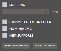
Select Snapping to enable snapping in fixed steps when using the mouse only, type the desired step value.
Select Dynamic Collision Checkcheck box to check the collision between supports and other parts while transforming parts.
Select Fix Minimum Z to keep the minimum Z height as the lowest position of parts. When the lowest point of the part(s) locates under or above the minimum Z height, the application automatically moves the part(s) up to the Minimum Z height.
Note: If you want to keep the lowest position of a part on zero (0) height location, clear the Fix Minimum Z option and move the part to the position by typing zero (0) in the Z of the Absolute Move option.
If supports exist, select Keep Supports to keep the position of supports along the movement of a part. This is available in the Print tab.
Click Reset Transform to reset the part transform or click Move to Origin to move the selected parts to the platform origin (0, 0, 0).
Move
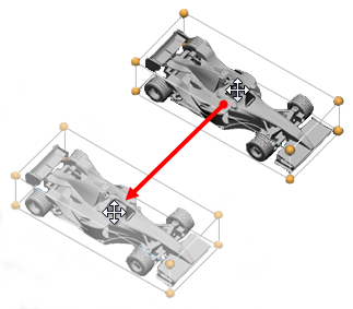
Move parts on the Print Platform.
Select a part and point to it. The cursor will change to a four-way arrow .
Left-click and drag. By default a part will move along the X and Y axis. To move along the Z axis, hold down the Alt key.
The part will snap to the platform boundary and floor when moving, hold Shift to disable this.
Note: If a part is moved outside of the printing volume, its outline will change to red.
To reset the part transform, click Reset Transform.
To move the part directly to the origin, on the command panel, click Move to Origin. It is useful if the part is far from the platform.
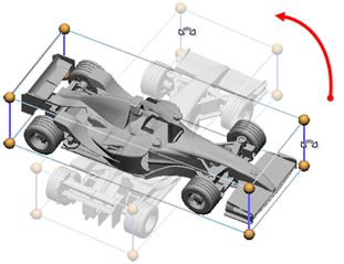
Rotate
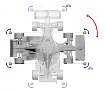
Rotate parts on the Print Platform. There are two ways to rotate a part:
When the viewpoint is perpendicular to the part, rotate-handles will appear. Grab one of the handles and drag to rotate.
Point at one of the bounding box edges, the corresponding edges will change color and a rotation axis will appear. Click and drag to rotate.
Note: By default a part will snap by 10 degrees while rotating using the mouse. To disable this, hold down the Shift key while rotating.
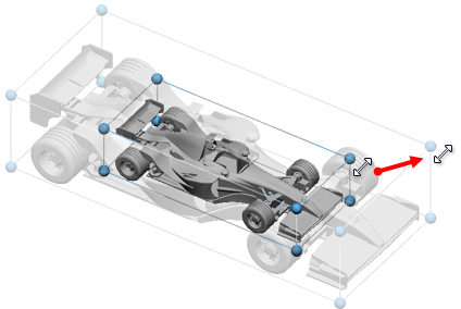
Scale
Scale parts, use the panel to scale differently in each axis.
Select Uniform Scaling to ensure the ratio of the parts bounding box is maintained when scaling.
Note: When scaling without the Uniform Scaling option checked, the resulting ratios between the width, length and height will be used when scaling uniformly at a later time.
To scale a part, point at a yellow handle and then left-click and drag.
Note: By default the tool will snap to even 10% scaling when using the mouse. To disable snapping, hold down the Shift key during the resizing.
Import / Export Transformation Matrix
After transforming an object, you can export a transform matrix of the moved object and import it to reuse it when transforming other objects.
Select a moved object from the parts list.
Right-click on a part or group, and select Transform > Export to export the transformation matrix as an .XML file.
Type a file name and click Save. The transformation matrix is exported.
To apply the exported transformation matrix to another part or group, right click on the part or group in the part list, and select Transform > Import.
Browse the exported transformation matrix file (.XML) and select it, and then click Open.