 Printer
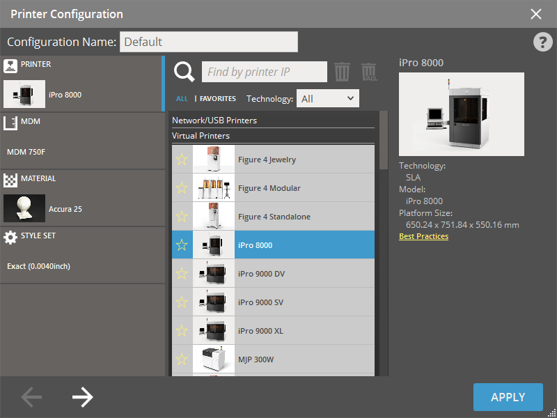
The Printer command opens the Printer Configuration window, enabling you to establish connections with printers and designate the current printer for configuring print job settings.
Note: The Manage Printer Configurations is only available when a real printer is connected.
Note: The Manage Printer Configurations is exclusively available for Ceramill printers.
Note: Features labeled with ![]() require a 3D Sprint Pro Subscription for access. For assistance, please reach out to our technical support team at http://www.3dsystems.com/support or contact your regional sales manager.
require a 3D Sprint Pro Subscription for access. For assistance, please reach out to our technical support team at http://www.3dsystems.com/support or contact your regional sales manager.
When selecting printer, click Apply to use previous or default settings, or go through each step by clicking the Next button ![]() to set up material, print mode and build style for the printer (there may be more steps depending on printer).
to set up material, print mode and build style for the printer (there may be more steps depending on printer).
Note: Click Back button ![]() to go back to the previous step or jump the step by clicking one of the steps in the Step List on the left-hand pane.
to go back to the previous step or jump the step by clicking one of the steps in the Step List on the left-hand pane.
After moving through the each step to set up material, print mode and build style for the printer and clicking Apply. These options will be the default for that printer and will be remembered the next time the printer is selected.
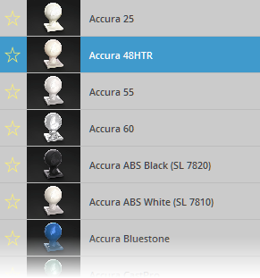
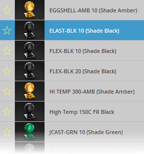
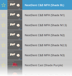
Note: To set your favorite printers and materials for later use, toggle on the yellow star button ![]() next to the printers and materials.
next to the printers and materials.
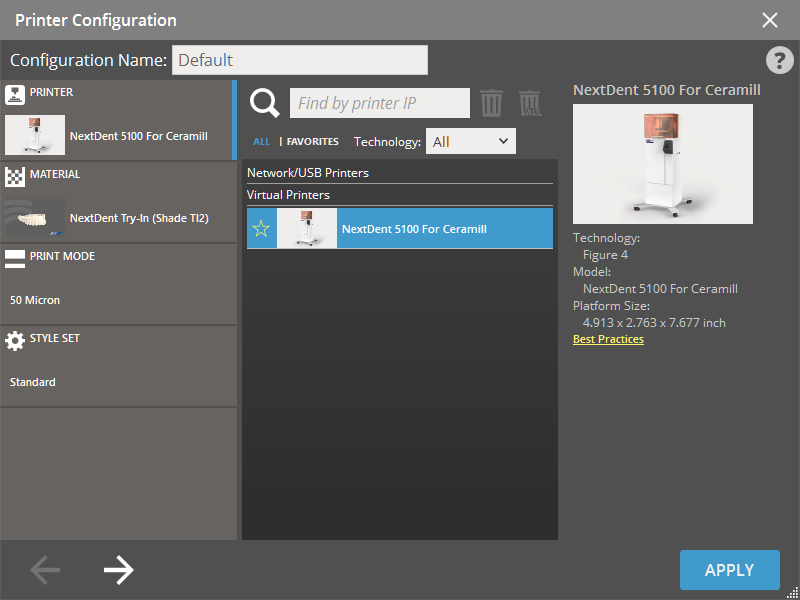
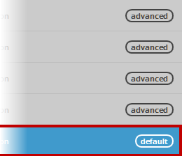
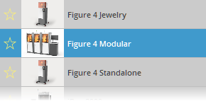
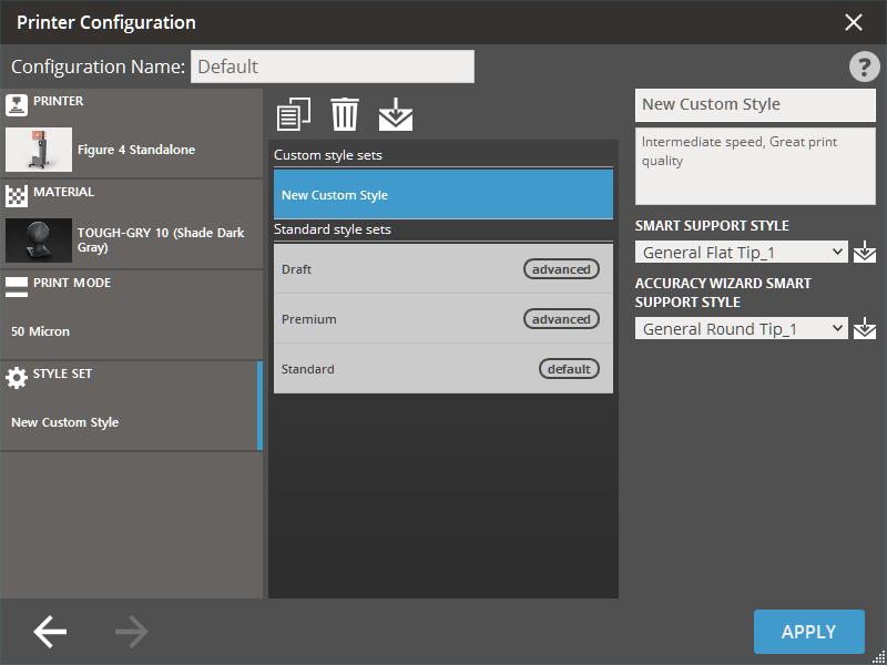
Note: (Figure 4 Printers) For some machine and material combinations a Print Mode and Build Style will recommend and marked as Default.
Note: To create a new custom printer configuration, use Manage Printer Configurations. In the Manage Printer Configurations, you can add multiple custom printer configurations and manage them for your print project. See Manage Printer Configurations for more information.
Steps
To complete the printer configuration for your print project, proceed the following steps. You can skip the step and use the default settings if there is no need to change.
|
Choose Printer |
|
|
|
|
|
|
|
Choose Printer |
|
|
|
|
|
Note: Set printer visibility in the Preferences. If a printer model is set as hidden it will not be visible in the Printer dialog.
To add a printer on the network or connected via USB, click Find Printer  .
.
If the printer is not detected (ex. if the printer is on a different sub-net):
-
Find the IP address of the printer, it is usually found on the display of the printer.
-
Type the IP address in the text field to search a printer by the IP address.

-
Click Find Printer
. The found printer is automatically added to the Printer List. -
To delete a printer, select one of the found printers and click Delete Selected Printer
 . To delete all found printers, click Delete All Printers
  .
.Note: Virtual Printers cannot be removed.
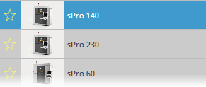
Set current printer
Select Printer for Best Results
Select printer to send print to before setting up the build. This allows for the most accurate results and the opportunity to create build styles for that specific printer.
-
Select a printer in the Printer List that will be used in the current project.


-
Click Apply to use the default or previous settings. To change the printer's settings, click Next
 or click on one of the steps in the Step List; MDM, Material, Print Mode, Build Style etc...
-
MDM (Material Delivery Module):
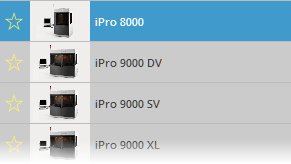
If the active printer is an SLA printer, select MDM. The Material Delivery Module (MDM) is the device that manages all subsystems related to the print material including printing a part. Each printer will have a set of pre-defined MDM size presets available for selection. For more information on the installation and use of the MDM, please consult your Hardware User Guide.
Custom MDM's can also be set by clicking Create
 on the Custom option.
And then entering the measured MDM size and click Next
to go to the next step, or click Back  to go back to the previous step.
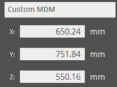
-
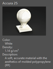
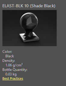
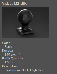
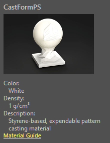
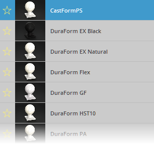
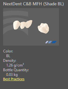
Select materials, a description of the material can be seen on the right-hand pane.
-
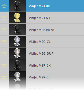
To load a material, click the material. It will then be highlighted.
-
To change a loaded material, select other loaded material.
-
Click Next
to go to the next step, or click Back to go back to the previous step.
-
-
Select materials, a description of the material can be seen on the right-hand pane.
-
To load a material, click the material. It will then be highlighted.
-
To change a loaded material, select other loaded material.
-
Click Next
to go to the next step, or click Back to go back to the previous step.
Note: For tips and information on materials for the Figure 4 series printers please see the Figure 4 Materials page.
-
-
Select materials, a description of the material can be seen on the right-hand pane.
-
To load a material, click the material. It will then be highlighted.
-
To change a loaded material, select other loaded material.
-
Click Next
to go to the next step, or click Back to go back to the previous step.
-
-
Select materials, a description of the material can be seen on the right-hand pane.
-
To load a material, click the material. It will then be highlighted.
-
To change a loaded material, select other loaded material.
-
Click Next
to go to the next step, or click Back to go back to the previous step.
Note: Material Guides for available SLS materials can be found here.
-
-
Select materials, a description of the material can be seen on the right-hand pane.
-
To load a material, click the material. It will then be highlighted.
-
To change a loaded material, select other loaded material.
-
Click Next
to go to the next step, or click Back to go back to the previous step.
-
-
Some printers allow the selection of a print mode. Select a Print Mode from the list and Click Next
to go to the next step, or click Back to go back to the previous step. -
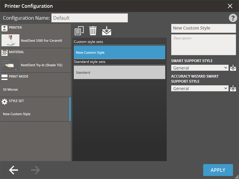
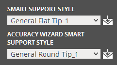
Select Build Style. For more information on managing custom build styles, see Manage Custom Build Styles.
Note: More information on default SLA build styles can be found here: SLA Build Styles
Note: Not all of the above options are available on all printer models.
-
-
Click Apply. All the updated settings are applied to the Print Platform and the Printer Configuration dialog will automatically be closed.
-
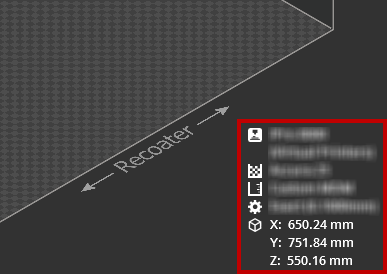
The application workspace will now be set according to the selected printer, material, print mode and build style.
Note: See the current printer, material and volume in the information box.
-
To set a custom printer configurations for your print projects, use the Configuration.
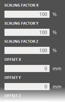
Create a new custom build style for your printer or edit advanced parameters as you desired.
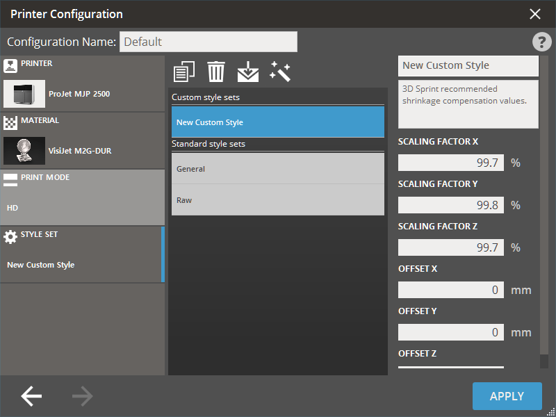
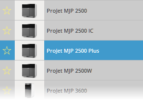
Note: The Offset X, Offset Y, and Offset Z options are available only for ProJet MJP 2500 and 2500 Plus.
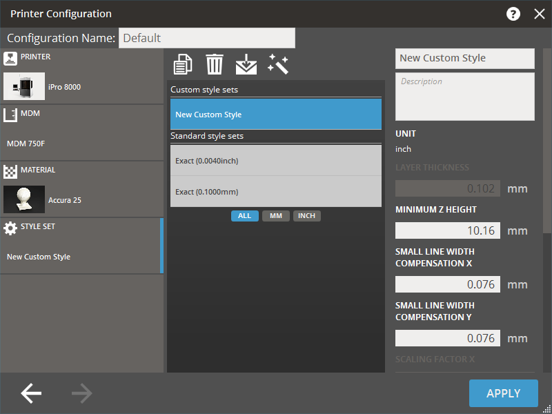
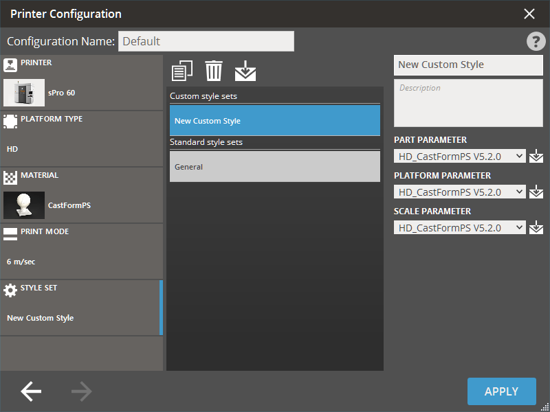
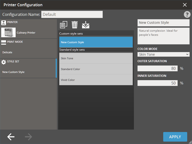
Create a new Style
-
Select one of the standard style presets in the list of style presets.
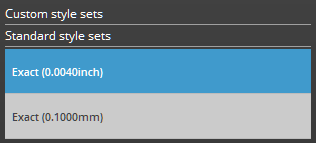
Note: A new style is created based on an existing preset.
Note: Click on any of the unit buttons to view the style based on the selected unit. Click All to view all available styles.
-
Click Copy
 .
.
-
Click Copy
.
-
Type a name in the Name input box and add a description in the Description input box if necessary. The name and description can be edited at anytime you need.
-
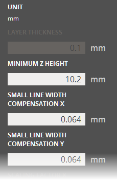
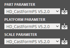
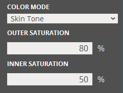
Set parameters in the right-hand pane as you desired.
-
Set parameters in the right-hand pane as you desired.
-
Set parameters in the right-hand pane as you desired.
-
Set parameters in the right-hand pane as you desired.
-
Set parameters in the right-hand pane as you desired.
-
If necessary, click Scale & Offset Wizard to open the Scale & Offset Wizard and calculate the optimal scale and offset values for the current printer.
-
Click Apply to apply the changes. The dialog will be closed.
-
To delete the created custom style. Select the style and click Delete
 .
.
Note: Style presets can be imported into the application using .3dpconfig files. It can be used to receive and use custom print presets developed by 3D Systems or other engineer. Click Import ![]() to import a preset and navigate to the preset file.
to import a preset and navigate to the preset file.
Export and import preset
Style presets can be imported into the application using .3dpconfig files. It can be used to receive and use custom print presets developed by 3D Systems or other engineer. A style preset can also be exported for storing and sharing with other users or 3D Sprint clients.
-
To export a preset to file, select the preset and click Export
 .
. -
Or, to import a preset, click Import
 and navigate to the preset file.
Scale & Offset Wizard
The Scale & Offset Wizard allows you to easily calculate the optimal scale and offset values for the current printer, based on measurement data entered with the Measure command.
-
Click Scale & Offset Wizard
 to open the Scale & Offset Wizard dialog.
 -
Once the scale and offset parameters are all set, click Apply to apply the changes.
Scale & Offset Wizard
The Scale & Offset Wizard allows you to easily calculate the optimal scale and offset values for the current printer, based on measurement data entered with the Measure command.
-
Click Scale & Offset Wizard
to open the Scale & Offset Wizard dialog. -
Once the scale and offset parameters are all set, click Apply to apply the changes.
Large Volume Mode
Many MJP printers have a access to a common feature, Large Volume Mode, in their printer settings. When enabled for parts with a large cross sectional area, the printing process will include an extra waiting time for cooling.
This will improve the quality of the printing job at the expense of increasing the printing time.
ProJet 2500 W and IC series printers have a similar option called Enhanced Cooling Mode that performs in a similar task.
Verification Strip Margin
The verification strip is a wall that is added to the print, it is used to verify that the printer’s nozzles or jets have been working correctly during the entire print. The Verification Strip Margin is available only for VisiJet® M2G-CL material used with ProJet 2500 printer. This prevents a part from being positioned in the non-recommended area while using the Transform command.
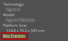
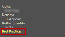
Best Practice Links
Best practice links for both printers and materials are shown when hovering over the printer or material. When connected to the internet, clicking on the Best Practices link will open the guides in a web browser.
 |
 |
|
Best Practices for Printer |
Best Practices for Material |
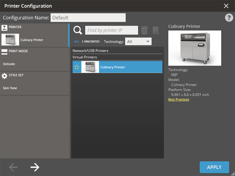
Use a virtual printer
Use a virtual printer to set up and verify a print without having the actual printer connected.
-
Select one of the virtual printers shown in the bottom of the dialog.
-
Follow the same steps as connecting to a printer.
USB connection
To connect the printer using USB connection additional drivers are required, they are usually installed at the same time as the application. The drivers can also be installed by:
-
Navigate to .../3D Sprint installation folder/Additional Drivers/ on your hard drive.
-
Select folder for printer model and double-click the installer file to begin installation.
See Also