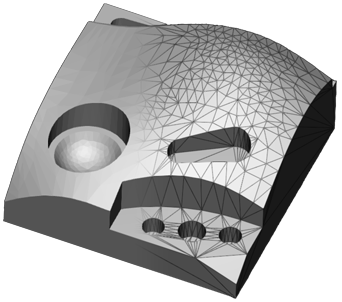
Parts are represented as triangle-meshes in the application. The mesh structure can have many sources:
The mesh consists of triangles, three vertices makes up a face:
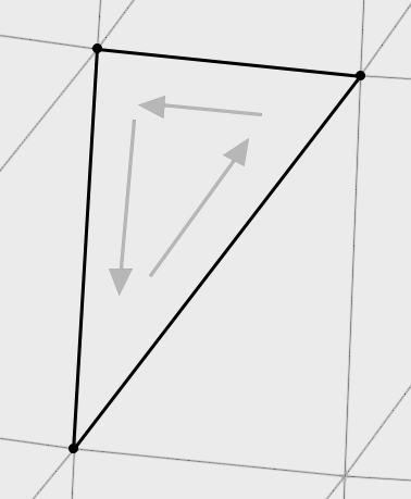
The order of the vertices defines the normal of the face.
Note: You can expose the mesh of a part by selecting Edge display in the View command.
Mesh Data Errors
Depending on source, the mesh data may have inherit errors or deficiencies. But to 3D print the part, the part mesh should be a closed mesh without errors. If the mesh has errors, such as holes or flipped faces, unexpected printing results may occur. So the mesh needs to be fixed before printing. Use the Fix command to fix part mesh errors.
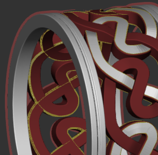
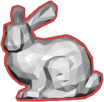
If a part mesh is analyzed to have errors, it is outlined red in the 3D view.
It is also marked with a red symbol in the printer list
Boundaries are marked with a yellow line in the 3D view.

And faces with inverted normals are colored red.