Supported Printers:
Figure 4 Printers
NextDent 5100
Supported Printers:
SLA-Printers
The Smart Support command allows the generation of a supporting structure to support parts during a build. Support structures function as scaffolding for the part during printing. The structures support the construction of parts and should be removed after the print is complete.
IMPORTANT: It is strongly recommended that you combine parts before creating supports if they may be colliding or interlocked. See Combine / Separate for more information.
To Create supports and edit support parameters or import and export support parameter settings.
Select one or more parts to create supports.
To save or load support parameters, use the Style group.
![]()
![]()
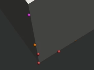
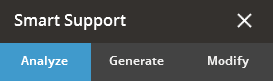
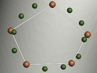
To only generate support anchor points, click Analyze.
To automatically create supports, go to the Generate tab and click Create.
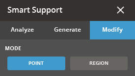
To manually place supports, go to the Modify tab.
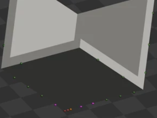
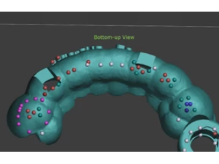
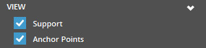
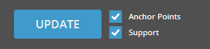
To view created supports and anchor points, use the Support and Anchor Points checkbox in the View group.
Note: The visibility of created supports can be toggled on and off by using the Show/Hide Supports button in the View Overlay found at the top corner of the working view.
![]()
![]()
![]() To view
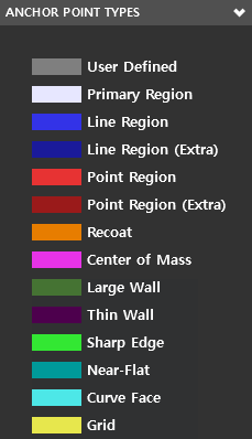
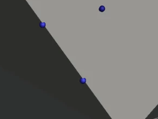
created anchor points by type, use the By Type
checkbox in the View group.
To view
created anchor points by type, use the By Type
checkbox in the View group.
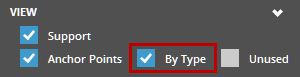
Note: The By Type option is available only when the Anchor Points option is selected. Click Here to see a list of Anchor Point Types.
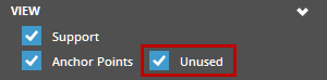
After creating supports, to view unused anchor points, use the Unused checkbox in the View group. This is available when the Anchor Points option is checked.
To view interface between the surface of the part and supports, use the Interface checkbox in the View group. This is available when the Support option is checked.

When finished editing supports, click Close (X).
Auto Supports
Automatically create a support structure.
In the Generate tab, edit the parameters as required.
Click Create.
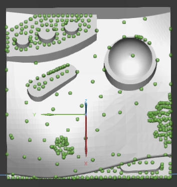
Generate Support Anchor Points
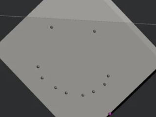
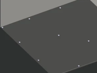
The support anchor points will now be displayed on the part,
but no supports will be generated.
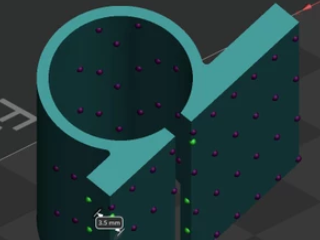
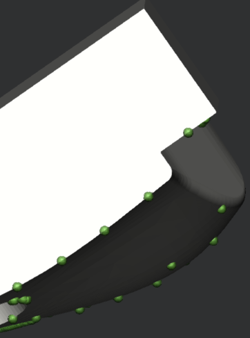
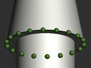
Edit Points and Regions
You can edit the anchor points, or the regions where the support is attached to the part.
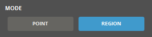
Go to the Modify tab, select Point to edit individual points or Region
to edit an area of the part.
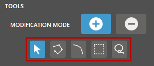
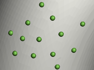
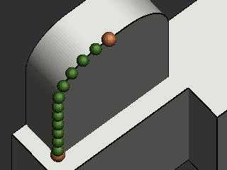
Anchor points can be seen as green balls on the part surface.
In the Modification Mode, click Add
![]() to add anchor points or click Erase
to add anchor points or click Erase ![]() to remove
them.
to remove
them.
Select the Strong option to set the locations of anchors for closed volume supports inside the standard Empire support.
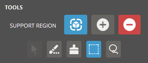
There are several selection tools to select region for creation
or existing anchor points for deletion. Click Done
![]() to accept the selection or click Discard
to accept the selection or click Discard ![]() to cancel the selection.
to cancel the selection.
![]() Point
- click to add an anchor point on a part surface or select an
existing point.
Point
- click to add an anchor point on a part surface or select an
existing point.
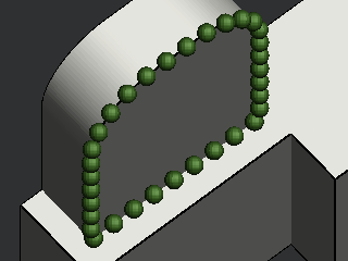
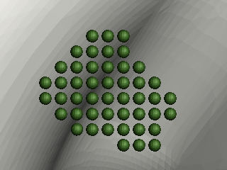
![]() Polyline
(Only available in the Add mode)
- click to draw a polyline on a part surface. Enter the spacing
and then create a polygonal shaped area with straight lines on
a part surface. Each time you click, a new line starts. Continue
clicking until it can be a closed loop to complete the polygonal
shape or double-click to complete the selection. Anchor points
are created on the lines of the polygonal shape with the specified
spacing.
Polyline
(Only available in the Add mode)
- click to draw a polyline on a part surface. Enter the spacing
and then create a polygonal shaped area with straight lines on
a part surface. Each time you click, a new line starts. Continue
clicking until it can be a closed loop to complete the polygonal
shape or double-click to complete the selection. Anchor points
are created on the lines of the polygonal shape with the specified
spacing.
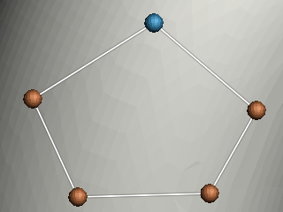
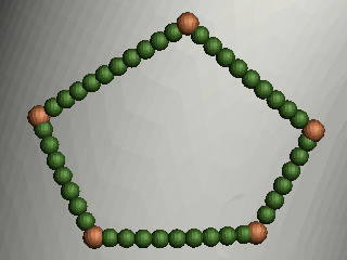
Note: To distribute anchor points on a virtual spline fitting to the vertices of the polygonal shape, click Fit.
![]() Edge (Only
available in the Add mode) - click
to select a sharp edge of a part. Enter the spacing and offset
distance, and then select a sharp edge of a part by using one
of the following edge selection methods: Loop,
Segment, and Start/End.
Anchor points are created on the selected edge with the specified
spacing. If the offset distance is specified, anchor points are
offset from the edge on the part surface.
Edge (Only
available in the Add mode) - click
to select a sharp edge of a part. Enter the spacing and offset
distance, and then select a sharp edge of a part by using one
of the following edge selection methods: Loop,
Segment, and Start/End.
Anchor points are created on the selected edge with the specified
spacing. If the offset distance is specified, anchor points are
offset from the edge on the part surface.
Loop - Finds a closed loop of an edge.
Segment - Selects a segment of an edge.
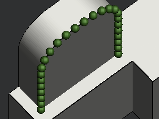
Start/End - Allows to define a start point and an endpoint of an edge.
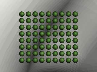
![]() Box -
click to draw a rectangle on a part surface. Enter the spacing
and then draw a rectangle area on a part surface. Grid anchor
points are created inside the rectangle with the specified spacing.
Box -
click to draw a rectangle on a part surface. Enter the spacing
and then draw a rectangle area on a part surface. Grid anchor
points are created inside the rectangle with the specified spacing.
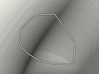
![]() Lasso
- click to draw a closed loop on a part surface. The loop automatically
closes when releasing the mouse button.
Lasso
- click to draw a closed loop on a part surface. The loop automatically
closes when releasing the mouse button.
Note: Pressing the CTRL key inverts the current modification mode. For example, If Add is selected, the CTRL key switches the mode to Erase.
Note: To move a point, click and drag the point to the desired position.
In the Tools, Region, Crease, Brush, Box, and Lasso allow for different ways to select editing regions.
Compute Regions ![]() allows the detection of downfacing regions and the visualization
of "Unsupported" regions of the part. This can be used
for the following two purposes:
allows the detection of downfacing regions and the visualization
of "Unsupported" regions of the part. This can be used
for the following two purposes:
For evaluation of automatically-generated anchor points
For evaluation of manually edited anchor points
Include ![]() allows selected region areas to be modified.
allows selected region areas to be modified.
Exclude ![]() allows the removal of previous edits.
allows the removal of previous edits.
Use the following shortcut keys to quickly add or clear region selections.
A - Select all regions as unsupported regions
C - Clear all the selections
R - Reverse the selections
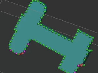
Defined regions are shown in green. Edited regions and faces are shown in red.
Red regions will not be used when generating supports.
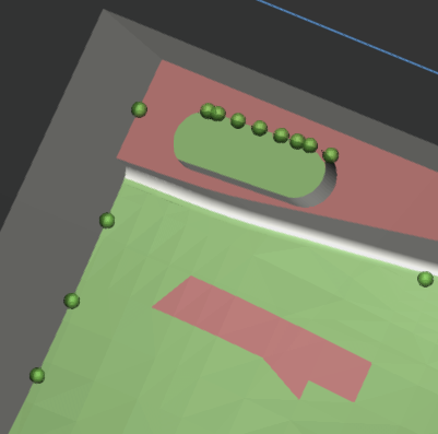
Click Create to generate supports, or if supports exist, select Support and click Update to update the supports with the changes.
Import and export parameters
Use the Style options to load and save your own custom styles. The styles are usually aimed at a particular class of models when they are best-utilized. The preset styles are offered with different stated goals.
![]()
Create a preset:
To
create a new preset, modify the support parameters as required and
click Add ![]() .
.
Create a name for the preset and click Set.
The preset should now be available from the Style Preset drop-down.
Update a preset:
To update a new preset, select the support parameters from the Style Preset drop-down.
Update the parameters for the support preset.
Click
Update ![]() to save
the changes or Restore
to save
the changes or Restore ![]() to reset the preset to
its initial value.
to reset the preset to
its initial value.
Rename a preset:
To
rename a preset, select the preset from the drop-down and click Rename ![]() .
.
Change the name for the preset and click Set.
The updated preset should now be available from the Style Preset drop-down.
Delete a preset:
To
delete a preset, select the preset from the Style
Preset drop-down and click Delete
![]() .
.
Import a preset:
To import support presets click Import
![]() below the Style
Preset drop-down.
below the Style
Preset drop-down.
Navigate to the parameter file and click Open.
Select the name for the preset and click Set.
Export a preset:
To export a preset, select the preset from the Style Preset drop-down.
Click Export ![]() below the Style Preset
drop-down.
below the Style Preset
drop-down.
Navigate to where you want to save the file, give it a name and click Save.
This will create a .styleddd file with your selected presets.
See Also