The Egg Shell Mold is designed to guide you through the process for creating vents, bridges, runners, and positioning sprue parts, and generating a final assembly for egg shell mold from a selected model.
Creating an Egg Shell Mold
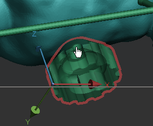
Select a model for egg shell molding.
In the Prepare tab, click Egg Shell Mold.
Select the Up Face option under the View option group to view the area that vents can be positioned.
Proceed to one of the following tools to create an egg shell mold from the model. You can switch between the tools freely regardless of the order.
![]() Vent
- Used to create vents which are the flow path of fluid into and
out of a mold.
Vent
- Used to create vents which are the flow path of fluid into and
out of a mold.
![]() Bridge
- Used to create connectors between vents.
Bridge
- Used to create connectors between vents.
![]() Runner
- Used to create runners which are the induction flow path of
the fluid.
Runner
- Used to create runners which are the induction flow path of
the fluid.
![]() Sprue
- Used to create sprue parts which are the vertical passage through
that liquid material is introduced into a mold.
Sprue
- Used to create sprue parts which are the vertical passage through
that liquid material is introduced into a mold.
![]() Shell
- Used to create a shell mold with added vents, bridges, runners,
and sprue parts.
Shell
- Used to create a shell mold with added vents, bridges, runners,
and sprue parts.
Note: If you have features that are not required, you can skip the process by clicking one of the other tabs.
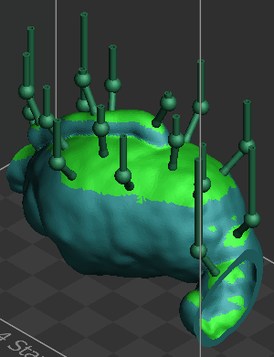
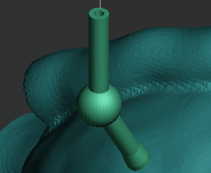
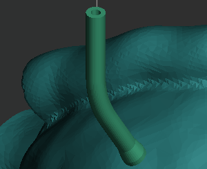
This manual process allows you to add new vents with geometrical parameters and position them on the surface of your model.
Go to the Vent tab ![]() to create vents.
to create vents.
Change the options and parameters as you desired. For more information on the details of the vent parameters, see Vent Parameters.
Click a point on a model to create a new vent.
Continue to create vents by clicking points on a model until all the desired vents are created.
Note: You can reposition the created vent by clicking and dragging its end-point that touches the surface of the model to a new position.
If necessary, you can delete the created vent by selecting and pressing the DEL key.
Go to the other tools to continue adding features to an egg shell mold.
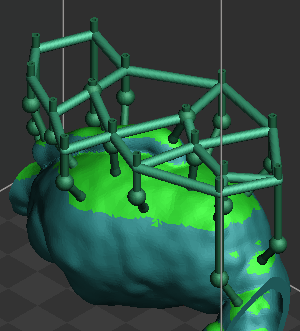
This manual process allows you to add new bridges between added vents. Created bridges are automatically updated when connected vents are moved to a new position.
Go to the Bridge tab ![]() to create bridges between
vents.
to create bridges between
vents.
Change the options and parameters as you desired. For more information on the details of the bridge parameters, see Bridge Parameters.
Click Apply to create bridges between existing vents.
If necessary, you can delete the created bridge by selecting and pressing the DEL key.
Go to the other tools to continue adding features to an egg shell mold.
This manual process allows you to add new runners with geometrical parameters and position them on the surface of your model.
Go to the Runner tab ![]() to create runners.
to create runners.
Change the options and parameters as you desired. For more information on the details of the runner parameters, see Runner Parameters.
Click two points on a model to create a new runner.
Continue to create runners by clicking two points on a model until all the desired runners are created.
Note: You can reposition the created runner by clicking and dragging its end-point that touches the surface of the model to a new position.
If necessary, you can delete the created runner by selecting and pressing the DEL key.
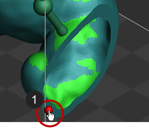
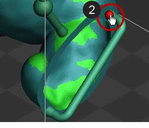
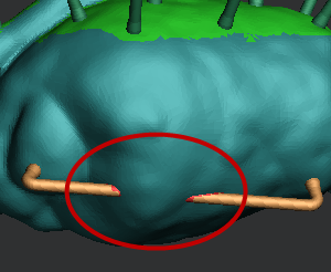
Select the Check Collision With Part option under the View option group to check if there are collisions between added features and the model.
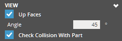
Note: If any collisions are detected, the conflicted features are displayed in orange and the collisions are displayed in red. Select the conflicted feature and change the parameters until its color becomes green to avoid collision with the model.
Go to the other tools to continue adding features to an egg shell mold.
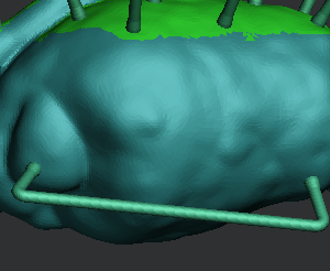
This manual process allows you to position sprue parts to your model.
Go to the Sprue tab ![]() to position a sprue
part to the model.
to position a sprue
part to the model.
Check if a part that can be used as a sprue part is loaded on the application. If no sprue part exists, go to File > Import and import a sprue part.
Click Select and select the part to use it as a sprue for the egg shell mold.
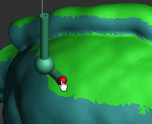
Click a point on a model to position the sprue part.
Note: You can reposition the added sprue part by clicking and dragging its end-point that touches the surface of the model to a new position.
Use the Move or the Rotate options to change the position of the sprue part. For more information on the options of the Sprue, see Sprue Options.
Click Apply to apply the changes to the model.
Repeat the step 3 to 6 to add sprue parts to the model.
If necessary, you can delete the created vent by selecting and pressing the DEL key.
Go to the other tools to continue adding features to an egg shell mold.
This automatic process allows you to create an egg shell model with added vents, bridges, runners, and sprue parts.
Go to the Shell tab ![]() to create a final assembly
for egg shell mold.
to create a final assembly
for egg shell mold.
Change the options and parameters as you desired. For more information on the details of the shell parameters, see Shell Parameters.
Click Apply to create an egg shell mold with added features.
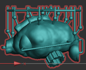
Check the results and click Close (X) to exit the command.
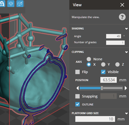
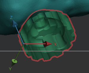
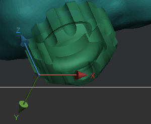
Go to the View panel and use the Clipping options to check the sections of the final assembly.
Options
Preset
Save parameter changes as defaults for later use and restore them at any time you need.
![]()
![]() Set Defaults
- Click to set parameter changes as defaults for later use.
Set Defaults
- Click to set parameter changes as defaults for later use.
![]() Restore
Defaults - Click to restore any changes to the saved defaults.
Restore
Defaults - Click to restore any changes to the saved defaults.
![]() Restore
Factory Defaults - Restores any changes to the factory defaults.
Restore
Factory Defaults - Restores any changes to the factory defaults.
![]() Import Saved
Parameters - Click to import saved parameters.
Import Saved
Parameters - Click to import saved parameters.
![]() Export Parameters
- Click to export changed parameters for later use.
Export Parameters
- Click to export changed parameters for later use.
Parameters
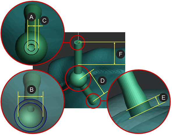
Int. Vent Diameter - The diameter of interior vent.
Int. Knee Diameter - The diameter of interior knee.
Sphere - Select to define the shape of knee as a sphere.
Spherical Knee
Basic Knee
Thickness - The thickness of vent.
Offset Distance - The offset distance of knee. Set a value to offset the knee by a specified distance from a zero point that touches on the surface of the model.
Penetration - The distance that the vent intersects with the model. From the nominal surface, higher values are inwards (opposite the direction of surface normal).
Extra Height - The height of vent above the upper bounds of the model. Set a value to add extra height to the vent.
|
|
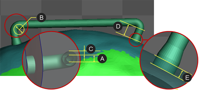
Diameter - The diameter of bridge.
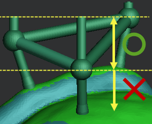
Offset - The offset distance of bridge. Set a value to offset the bridge by a specified distance from a top point of vents.
Note: The offset distance is limited to be set lower than the knee position.
Int. Runner Diameter - The diameter of interior runner.
Int. Knee Diameter - The diameter of interior knee of the runner.
Thickness - The thickness of runner.
Offset Distance - The offset distance of knee. Set a value to offset the knee by a specified distance from a zero point that touches on the surface of a model.
Penetration - The distance that the runner intersects with the model. From the point of intersection on the surface of the model to where the runner ends, higher values are inwards. (opposite the direction of surface normal)
|
|
Move - Set values to move a sprue part along X-, Y-, and Z-Axis of a local coordinate system.
Rotate - Set values to rotate a sprue part around X-, Y-, and Z-Axis of a local coordinate system.
Flip - Select to reverse the Z-direction of a sprue part.
Sprue Part
Reversed Sprue Part
Note: The local coordinate system of a sprue part is automatically defined based on the normal direction of a selected polygonal face.
Thickness - The outer thickness of the shell.
Type - Select either CAD or Scan depending on the type of the model.
Apply Fix - Select to fix defects on the mesh before shelling. This option is available when the Scan type is selected.
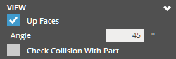
View
Up Faces - Enable up face display to see overhangs and features that vents can be added to.
Angle - Threshold angle for up face display.
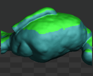
Up Faces - 45° (Degrees)
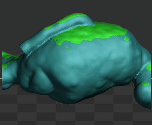
Up Faces - 30° (Degrees)
Check Collision With Part - Allows checking the collision with the target part while adding mold features. If any collisions are detected, the conflicted features are displayed in orange and the collisions are displayed in red. Select the conflicted feature and change the parameters until its color becomes green to avoid collision with the target part.
See Also